
Automotive Circuit
Index 66
the control circuit of the temperature controller(12)
Published:2011/6/26 5:00:00 Author:Ariel Wang | Keyword: temperature controller, control
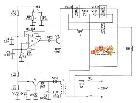
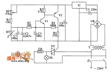
When the mains switch S2 gets through,the 220V AC voltage is reduced by T,commutated by VD1,filtered by C4,regulated by V1 and V2.It provides +12V working voltage for IC and VLC2.At the same time,it lights VL by R3.When the power supply is on,the temperature in the hatching house is lower than the set temperature.The resistence of the temperature sensor RT is large.The pin-6 of IC(output end) outputs high level as the voltage of pin-3(the non-inverting termina) is higher than the voltage of pin-2(the inverting termina).V2 is conducted.The LEDs in YLC1 and YLC2 are lighted. The photodiode is conducted.VT is triggered to conduct.The electric heater EH is conducted to work. (View)
View full Circuit Diagram | Comments | Reading(384)
the control circuit of the common electric motor(2)
Published:2011/6/25 21:09:00 Author:Ariel Wang | Keyword: control circuit, common, electric motor

The main circuit of the electric motor consists of Q,FU,the normally open main contact KM1 of KM and thermoelement of the thermal relay KR.The control circuit consists of S,KM,KA1,KA2 and the normally closed contact of KR.When you want to start it,the knife switches need to get through.When S is pressed,KA1 is conducted to pull in.The normally open contacts KAI-1 and KAI-3 get through.The normally closed contact KAI-2 is disconnected.KM is conducted to pull in.The normally open main contact KM1 and the normally open auxiliary contact KM3 and KM4 are connected.M starts to work.When S is disconnected.KA1 is released.KM stays pull-in as the contact KM4 is working.You can press S again when you want to stop it,KA2 is conducted to pull in.The normally open contact KA2-2 is connected.The normally closed contact KA2-1 and KA2-3 are disconnected.KM is released.M stops working.
(View)
View full Circuit Diagram | Comments | Reading(1653)
the control circuit of the common electric motor(4)
Published:2011/6/25 20:13:00 Author:Ariel Wang | Keyword: control, common, electric motor
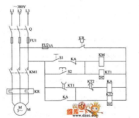
When you use it,Q and 51 need to get through.Then KM and KT1 are conducted to pull in.M works.After it works for a while,the normally open contact of KT1 which is delayed to close makes KA and KT2 conduct to pull in.And the normally closed contact of KA is disconnected.KA is released.The normally closed contact of KA is connected.KM and KT1 are conducted to pull in.M works.It goes on and on,M works at an interval time.If S2 is pressed when KM is released and M stops working,KM is pulled in.M starts to work immediately. (View)
View full Circuit Diagram | Comments | Reading(510)
the control circuit of the temperature controller(15)
Published:2011/6/25 20:01:00 Author:Ariel Wang | Keyword: control, temperature controller
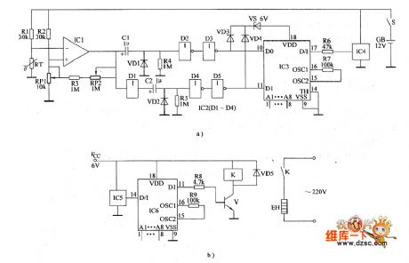
When the mains switch S gets through,temperature detection wireless transmission circuit is conducted to work.When the enviroment temperature in the controlled place is lower than the controll temperature set by RP1.The resistence of RT increased to a certain value,IC1 outputs low level.The not gate D1 of IC2's in-circuit outputs high level.It charges C2.When C2 is fully charged(about 1s).Not gate D2 outputs positive pulse.The pin-11 of IC3 outputs code signal.It is emitted by IC4's modulation.After IC5 recieves the modulated code signal emitted by IC4,it is decoded by IC6.The pin-11 of IC6 outputs steady high level.V is saturated to conduct.K is conducted to pull in.The electric heater EH is conducted to heat. (View)
View full Circuit Diagram | Comments | Reading(431)
Oxidation-reduction for ozone in the water concentration monitor hardware circuit
Published:2011/6/20 5:46:00 Author:John | Keyword: concentration monitor
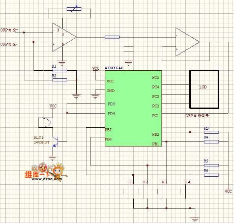
The circuit mainly includes: single-chip’s main control part, signal acquisition and processing, display part, keyboard part, alarm circuits and two control outputs. The hardware circuit to achieve the automatic measurement of ozone concentrations is to achieve the pick-up of signals. ORP sensor is used here, whose output signals are directly into the amplifier AD620. AD620 is a differential input amplifier, which is with zero drift. Its input resistance is 1 × 10¹⁰Ω, which can meet the needs of ORP sensor. It also can achieve the impedance conversion function.
(View)
View full Circuit Diagram | Comments | Reading(1242)
LTC1043 frequency control gain amplifier circuit
Published:2011/6/20 5:34:00 Author:John | Keyword: gain amplifier
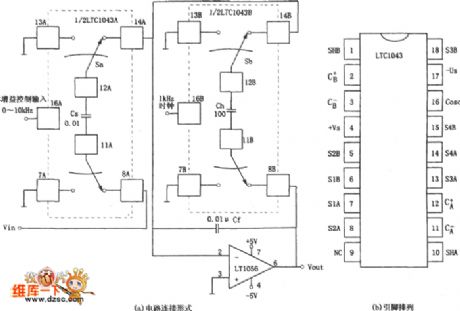
The figure shows gain amplifier circuit controlled by frequency. Different input clock frequencies are used to control the amplifier’s gain circuit, thus being called the frequency gain control circuit. Figure (a) shows that the circuit consists of two parts: analog switch and integrated amplifier. Analog switch consists of two pieces of precision capacitor switches LTC1043 and integrated amplifier uses the JFET input type op-amp LT1056.
(View)
View full Circuit Diagram | Comments | Reading(655)
ISO122 programmable gain isolation amplifier circuit
Published:2011/6/20 0:10:00 Author:John | Keyword: isolation amplifier
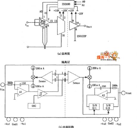
The figure shows the programmable gain isolation amplifier circuit. The circuit makes use of the isolation amplifier ISO122’s isolation performance and PGA102’s programmable gain controlling function. It also uses a two-way digital coupler ISO150 with isolation performance, in order to achieve the isolation for the input / output signals and gain control signals. Figure (b) is the internal block diagram for the ISO122.
(View)
View full Circuit Diagram | Comments | Reading(858)
Reader and transponder 2ASK modem circuit
Published:2011/6/19 23:54:00 Author:John | Keyword: modem, Reader, transponder
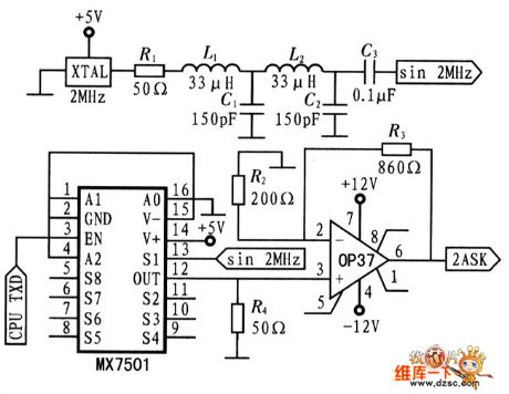
2ASK’s carrier signal is 2MHz sine wave. It achieves crystal of the square wave through a low pass filter. Digital modulation signal is output from the CPU's serial port and the signals are controlled to on or off through the analog switch MX7501, resulting in 2ASK signals. L1, L2, C1 and C2 constitute the second-order Butterworth low-pass filter, whose output is approximately sine wave’s 2 MHz signals. R1 and R4 lead to the matching of the LC filter impedance. When EN is 0, the OUT is 0; vice versa for the S1 channel signal. The following figure shows the reader’s 2ASK modulation circuit.
(View)
View full Circuit Diagram | Comments | Reading(526)
the control circuit of the common electric motor(5)
Published:2011/6/25 20:14:00 Author:Ariel Wang | Keyword: control, common , electric motor
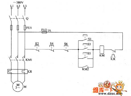
When the circuit is installed,you should install 51 abd S2,53 and 54,55 and 56 at three places.At the first place,when 51 is pressed,KM is conducted to pull in.The normally open contact is conducted.M works.When 52 is pressed,KM is released.M stops working.In the same way,when 52 is pressed at the second place or when 55 is pressed at the third place,KM will pull in.M works.When 54 or 56 is pressed.KM will release.M stops working.In this way,the electric motor can be controlled at three places.If you want to have more places to be controlled,you can just connect normally open control button in parallel or connect normally closed control button in series. (View)
View full Circuit Diagram | Comments | Reading(414)
Voltage-tuned NE-602 oscillator circuit
Published:2011/6/19 4:58:00 Author:John | Keyword: oscillator
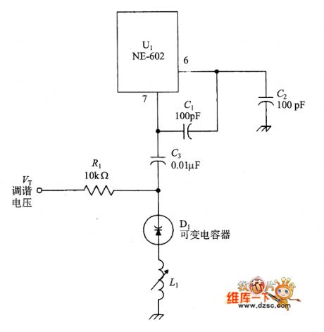
Figure shows a pair of tuned circuits. The capacitor unit is the variable voltage capacitor diode or varactor VFO circuit. Diode display equivalent of junction capacitance for its upon reverse bias. Thus, the frequency of the oscillator circuit can be controlled by the tuning voltage Vt.
NE-602 is a RF chip with good performance. It can be used in a variety of receivers, converters, oscillators, signal generators and other equipment.
figure: Voltage-tuned NE-602 oscillator circuit (View)
View full Circuit Diagram | Comments | Reading(660)
the circuit of temperature controller(16)
Published:2011/6/25 19:20:00 Author:Ariel Wang | Keyword: temperature controller
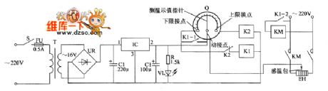
When the mains switch gets through,the 220V AC voltage is reduced by T,commutated by RU,filtered by C1 and regulated by IC.Then it generates +12 voltage.It is for the temperature detect control circuit.At the same time,VL is lighted by R.When you use it,you can set the upper limit and lower limit of temperature by the thermelometer Q.When the controlled temperature is lower than the lower limit of the temperature,the moving contact of Q is connected with the contactor of the lower limit.The relay K1 and KM are conducted to pull in. EH is conducted to heat.When the temperature rises,the moving contact of Q is disconnected with the contactor of the lower limit.But as the normally open contacts K1-1 of K1 is closed,K1 and KM stay pull-in.EH stays conducted.
(View)
View full Circuit Diagram | Comments | Reading(354)
the circuit of temperature controller(17)
Published:2011/6/23 6:54:00 Author:Ariel Wang | Keyword: temperature controller
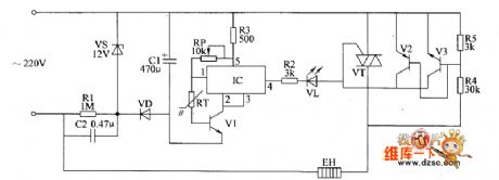
The 220V AC voltage is reduced by C2,regulated by VS,commutated by YD and filtered BY c2.It provides 11.3V DC working voltage for the temperater control circuit.RP is used to set the control temperature value.When the environment temperature in the controlled place is detected lower than the set temperature by RT,the in-circuit of IC works.VT is conducted.The electric heater EH is conducted to work.The resistence of RT becomes lower when the temperature becomes higher.When the controlled temperature becomes the temperature set by RP,the in-circuit of IC stops working.VT is stopped.EH stops heating.When the temperature becomes lower than the set temperature,VT is conducted again.EH is conducted to work. (View)
View full Circuit Diagram | Comments | Reading(382)
bistable transconductance mixer used in NE-602 circuit
Published:2011/6/21 0:12:00 Author:John | Keyword: bistable transconductance mixer
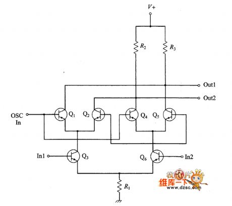
Bistable transconductance mixer used in NE-602 circuit is shown.
(View)
View full Circuit Diagram | Comments | Reading(637)
the circuit of temperature controller(18)
Published:2011/6/23 6:25:00 Author:Ariel Wang | Keyword: temperature controller
RP is used to set the temperature control point.When the resistence of RP is adjusted to a low level,the temperature control point goes up.Otherwise,the temperature control point goes down.When the temperature in thermotank is higher than the set control temperature by RP,the base voltage is lower than 0.6V.V1,V2 and V5 are all stopped.The electric heater EH stops working.HL is not lighted.When the temperature in thermotank is lower than the set control temperature by RP,the base voltage of V1 is higher than 0.6V.V1 and V2 are saturated to conduct.The output voltage of V2's collector goes to VT's gate by R5.VT is triggered to conduct.EH is conducted to heat.HL is lighted. (View)
View full Circuit Diagram | Comments | Reading(400)
TA7291S electric motor driving integrated circuit
Published:2011/6/16 0:59:00 Author:chopper | Keyword: electric motor, driving, integrated
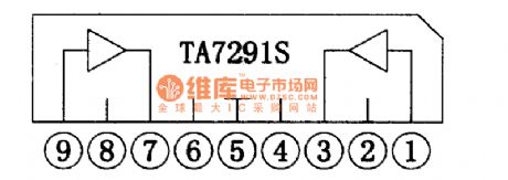
TA7291S is a bidirectional control motor driving integrated circuit produced by Company TOSHIBA.It is applied to laser player to the load motor drive.1.The inner circuitTA72915 integrated circuit includes two motor driving integrated circuits.Its inner circuit is shown as picture 1.
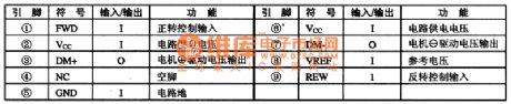
2.function of pinsTA72915 integrated circuit adopts 9 pins single inline package.Its functions of pins of integrated circuitare shown as chart 1.
(View)
View full Circuit Diagram | Comments | Reading(1673)
TA212lF servo driving integrated circuit
Published:2011/6/16 22:06:00 Author:chopper | Keyword: servo, driving, integrated circuit
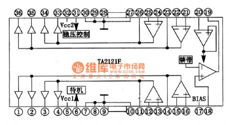
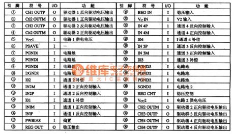
TA2121F is a monolighic servo driving integrated circuit produced by Company TOSHIBA,and it is applied to TOSHIBA DVD players widely.1. The inner circuitTA2121F integrated circuit includes 4 channels BTL driving circuit which can receive DWM control signal output by digital servo IC.And the signal will be amplified by inner wave filtering and drive to drive the corresponding executive components.Its inner circuit of integrated package are shown as picture 1.
2.function of pins TA2121F integrated circuit adopts dual inline 36 pinned package.This chip is of cooling fin.Its function pins of the integrated circuit are shown as chart 1.
(View)
View full Circuit Diagram | Comments | Reading(434)
Shanghai Buick Royaum V63.6L car air conditioning system circuit diagram(3)
Published:2011/6/24 4:23:00 Author:Nicole | Keyword: Shanghai Buick Royaum, car, air conditioning system
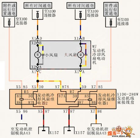
View full Circuit Diagram | Comments | Reading(412)
Shanghai Buick Royaum V63.6L car fuel system control circuit diagram(3)
Published:2011/6/24 4:24:00 Author:Nicole | Keyword: Shanghai Buick Royaum, car, fuel system control
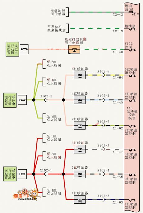
View full Circuit Diagram | Comments | Reading(358)
Shanghai Buick Royaum V63.6L car air flow and inlet temperature sensor circuit diagram
Published:2011/6/24 4:27:00 Author:Nicole | Keyword: Shanghai Buick Royaum, car, air flow, inlet temperature sensor
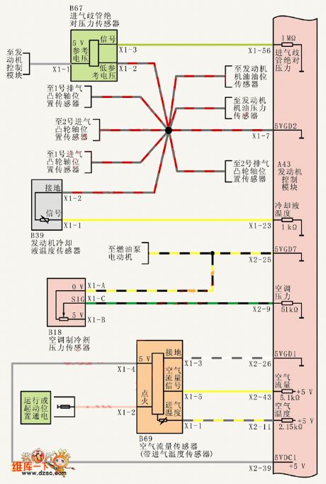
View full Circuit Diagram | Comments | Reading(368)
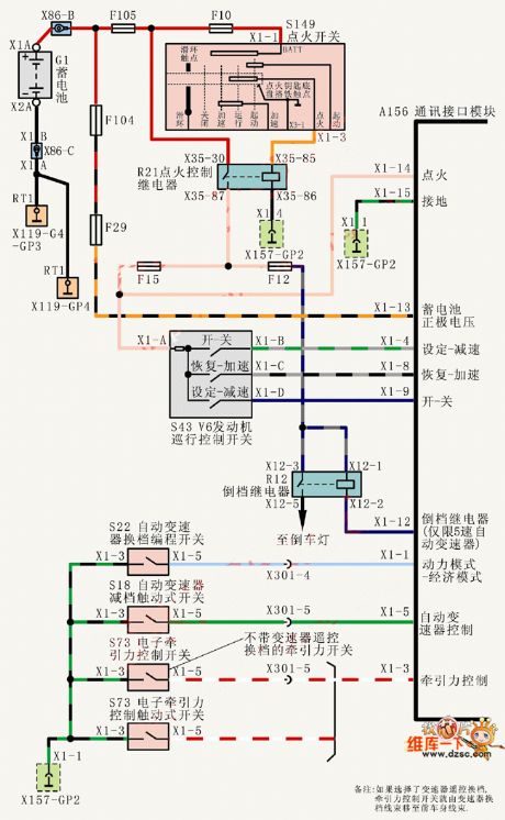
Shanghai Buick Royaum V63.6L car dynamical system interface module circuit diagram
Published:2011/6/24 4:30:00 Author:Nicole | Keyword: Shanghai Buick Royaum, car, dynamical system, interface module
View full Circuit Diagram | Comments | Reading(386)
| Pages:66/164 At 206162636465666768697071727374757677787980Under 20 |
Circuit Categories
power supply circuit
Amplifier Circuit
Basic Circuit
LED and Light Circuit
Sensor Circuit
Signal Processing
Electrical Equipment Circuit
Control Circuit
Remote Control Circuit
A/D-D/A Converter Circuit
Audio Circuit
Measuring and Test Circuit
Communication Circuit
Computer-Related Circuit
555 Circuit
Automotive Circuit
Repairing Circuit