Automotive Circuit
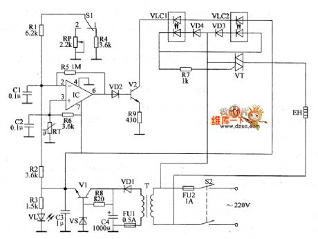
the control circuit of the temperature controller(12)
Published:2011/6/26 5:00:00 Author:Ariel Wang | Keyword: temperature controller, control | From:SeekIC

When the mains switch S2 gets through,the 220V AC voltage is reduced by T,commutated by VD1,filtered by C4,regulated by V1 and V2.It provides +12V working voltage for IC and VLC2.At the same time,it lights VL by R3.When the power supply is on,the temperature in the hatching house is lower than the set temperature.The resistence of the temperature sensor RT is large.The pin-6 of IC(output end) outputs high level as the voltage of pin-3(the non-inverting termina) is higher than the voltage of pin-2(the inverting termina).V2 is conducted.The LEDs in YLC1 and YLC2 are lighted. The photodiode is conducted.VT is triggered to conduct.The electric heater EH is conducted to work.
Reprinted Url Of This Article:
http://www.seekic.com/circuit_diagram/Automotive_Circuit/the_control_circuit_of_the_temperature_controller12.html
Print this Page | Comments | Reading(3)

Article Categories
power supply circuit
Amplifier Circuit
Basic Circuit
LED and Light Circuit
Sensor Circuit
Signal Processing
Electrical Equipment Circuit
Control Circuit
Remote Control Circuit
A/D-D/A Converter Circuit
Audio Circuit
Measuring and Test Circuit
Communication Circuit
Computer-Related Circuit
555 Circuit
Automotive Circuit
Repairing Circuit
Code: