Automotive Circuit
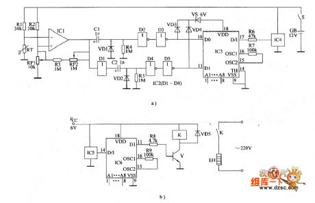
the control circuit of the temperature controller(15)
Published:2011/6/25 20:01:00 Author:Ariel Wang | Keyword: control, temperature controller | From:SeekIC

When the mains switch S gets through,temperature detection wireless transmission circuit is conducted to work.When the enviroment temperature in the controlled place is lower than the controll temperature set by RP1.The resistence of RT increased to a certain value,IC1 outputs low level.The not gate D1 of IC2's in-circuit outputs high level.It charges C2.When C2 is fully charged(about 1s).Not gate D2 outputs positive pulse.The pin-11 of IC3 outputs code signal.It is emitted by IC4's modulation.After IC5 recieves the modulated code signal emitted by IC4,it is decoded by IC6.The pin-11 of IC6 outputs steady high level.V is saturated to conduct.K is conducted to pull in.The electric heater EH is conducted to heat.
Reprinted Url Of This Article:
http://www.seekic.com/circuit_diagram/Automotive_Circuit/the_control_circuit_of_the_temperature_controller15.html
Print this Page | Comments | Reading(3)

Article Categories
power supply circuit
Amplifier Circuit
Basic Circuit
LED and Light Circuit
Sensor Circuit
Signal Processing
Electrical Equipment Circuit
Control Circuit
Remote Control Circuit
A/D-D/A Converter Circuit
Audio Circuit
Measuring and Test Circuit
Communication Circuit
Computer-Related Circuit
555 Circuit
Automotive Circuit
Repairing Circuit
Code: