
Automotive Circuit
Index 77
The FAW Toyota-Reiz engine control diagram (1)
Published:2011/6/10 1:35:00 Author:Seven | Keyword: Toyota-Reiz, engine control

See as the figure, this is the FAW Toyota-RuiZhi engine control diagram (1) (View)
View full Circuit Diagram | Comments | Reading(472)
The Faw Toyota-Reiz cooling fan diagram
Published:2011/6/9 0:18:00 Author:Seven | Keyword: Toyota-Reiz, cooling fan

See as the figure. The Faw Toyota-Reiz cooling fan diagram (View)
View full Circuit Diagram | Comments | Reading(520)
The outline circuits of some digital boards
Published:2011/6/10 0:56:00 Author:qqtang | Keyword: outline circuit, digital board

The digital board consists of special integrated circuits, highly stable reference power supply and digital display components. The digital board characterizes high precision, strong antijamming capability, good reliability, wide working temperature and convenient installation, which is a replacement of the pointer type. The digital board can be directly used in all kinds of electricity parameter tests, such as working with sensors, and it can also be used in non-electricity parameter tests, such as military strength, temperature and movement,etc.
Figure: The outlines of some digital boards (View)
View full Circuit Diagram | Comments | Reading(410)
the control circuit of electric fence part 8
Published:2011/6/2 6:20:00 Author:Ariel Wang | Keyword: control, electric, fence
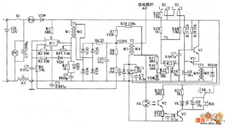
After the mains switch S1 gets through, autogenerator works.It generates oscillating impulse voltage on the W2's winding of T1.The oscillating impulse voltage is commutated by VD1 and VD4.It charges C10 by R6.When C10 is full charged and the voltage through C10 reaches +320V,the 2nd-pin of IC1 becomes high level.The autogenerator stops.When the metal wire of the electric fence is not touched by any animals ,IC2 is conducted.C5 is charged.V1 and VU are off condition.The trigger control circuit has no voltage output.VT is not conducted.There is no pulsed high voltage generated on the W4's winding of T2.The alarm circuit doesn't work.VL is not lighted. HA doesn't ring.
(View)
View full Circuit Diagram | Comments | Reading(2420)
the control circuit of electric fence part 7
Published:2011/6/3 8:21:00 Author:Ariel Wang | Keyword: control, electric, fence


The AC 220V voltage is reducted by T1 isolated.It is commutated by VD1-VD4.It is filtered by C1.And it is current limited by R1.It charges C2.It is branched by R2,VS,RP and R3.It provides trigger voltage for VT's gate.When the voltage of C2 is charged to a certain value,VT is triggered to conduct.C2 discharges on VT and the first winding of T2.After C2 discharges,VT stops.C2 begins to charge,so VT conducts……It goes over and over again.It will generate kilovoltage pulsed high voltage on the second winding of T2.The high voltage of the electric fence will give the animal touching it an electric shock.
(View)
View full Circuit Diagram | Comments | Reading(1892)
the control circuit of electric fence part 5
Published:2011/6/5 19:38:00 Author:Ariel Wang | Keyword: control, electric, fence

The 6V AC voltage is commutated by VD8-VD11.It is filtered by C5.It provides +6V working voltage for triggering the control circuit and protecting the circuit.It is reduced by R9,and it will go to VL3.Then it lights VL3.The 1500V AC voltage goes to the aerial bare metal line of electric fence by control turns L1 and L2.If the aerial bare metal line is not touched by any animals and there is no current in the control turns L1 and L2 ,control contacts of reed switches SA1 and SA2 are off state.V1-V4 stop.K1 and K2 are at release position.The alarm circuit is not working.VL1 and VL2 are not be lighted.BL don't give a sound.
(View)
View full Circuit Diagram | Comments | Reading(558)
the circuit of electrifying intermittent controller part 2
Published:2011/6/5 20:34:00 Author:Ariel Wang | Keyword: electrifying, intermittent, controller

After the multivibrator conducted to work, the output cycle from 3rd-pin(Q14 end) of square-wave pulse is 1 min.It is the counting pulse of the 14th-pin of IC2.It outputs a high level every 10 min or 6 min(position 53 on 1 ,the control circuit will work for 1 min every 10 min;position 53 on 2 ,the control circuit will work for 1 min every 6 min).V will conduct when the 3rd-pin of IC2 outputs high level.It will light LED inside VLC.The photo-thyristor will conduct by exposed to sunlight.The controlled electric appliance will be conducted to work.
(View)
View full Circuit Diagram | Comments | Reading(463)
the circuit of timing controller part 2
Published:2011/6/8 9:19:00 Author:Ariel Wang | Keyword: timing , controller

When you reach the timing time (5min),it outputs high level from Y5 end of IC2.The trigger ItS overturns to D1.D4 outputs high level.D2 and D3 output low level.K releases.The normally open contacts cut off the working power supply of load.At the same time,VL dies out.At this moment,if S3 at the position 9 of single timing ,then the time of timing goes back.IC2 stops counting.If S3 at the position of circulation ,then IC2 goes on counting.After 5MIN,the end of YO outputs high level.Trigger RS overturns.K pulls back again. The load is conducted to work.The timing time (5min) goes back,Y5 end of IC2 outputs high level,trigger ItS overturns again……The circle goes on,the load intermittent works.
(View)
View full Circuit Diagram | Comments | Reading(501)
the circuit of humidity detector for food part 1
Published:2011/6/8 16:18:00 Author:Ariel Wang | Keyword: humidity , detector, food

When to be detected,the foodstuffs are put into the space between two metal plates of the capacitive humidity sensor.The humidity amount of foodstuffs is changing as the capacity changes.Then the oscillation frequency of multivibrator is changing as well.The shortwave signal which outputs from the pin-3 of IC becomes triangular wave signal.It becomes DC voltage after it is commutated by VD1 and VD2.It reveals itself through voltmeter PV(the more amount of the food humidity,the larger capacity of the sensor,and the higher of the voltage PV displays).
(View)
View full Circuit Diagram | Comments | Reading(419)
the circuit of the timing controller part 1
Published:2011/6/8 23:22:00 Author:Ariel Wang | Keyword: timing, controller

S1 is used to change the time set,the walking state and the timing set of the timing controller.When it's at state of time set,S2 is used to convert and regulate the position of hours and minutes. S3 is used to quicken the time.S4 is used to slow down the time.When to set the timing time,S2 can convert and set the work station of whether work or not at some timing time.At the state of walking,S2 is used to enter or exit the manual state.S3 is used to turn the power of the equipment on.S4 is used to shut down the power of the equipment.
(View)
View full Circuit Diagram | Comments | Reading(423)
the substitute circuit of electric motor centrifugal switch part 2
Published:2011/6/9 0:14:00 Author:Ariel Wang | Keyword: substitute, electric, motor, centrifugal, switch

When power supply gets through,the voltage can't change suddenly as the capacity of CZ is larger.And the relay K can't pull in.After a few minutes,the voltage of C2 is charged to a certain value(when the input AC voltage is in the positive half cycle ,it charges C1 by VD1.When the input voltage is in the negative half cycle,the voltage charged by C1 and input voltage are added together.Then it charges C2 by VD2. )K is conducted to pull in.The normally-closed contacts are disconnected.It breaks the starting circuit of M.The main winding of M works alone.It completes the starting process of electric motor.
(View)
View full Circuit Diagram | Comments | Reading(917)
the control circuit of electric fence part 1
Published:2011/6/9 7:07:00 Author:Ariel Wang | Keyword: control, electric, fence

When the mains switch gets through,the 220V AC voltage is reduced by T1,commutated by UR,filtered by C1,current limited by R1 and regulated by VS.Then it generates 12V DC voltage.It is the power supply for the working of alarm HA and relay K.EL1 and the primary winding T3 are parallel connected.They and the primary winding of transformer booster T2 are series connected.After S gets through,neon indicator HL is lighted.But EL1 is not shining as the electric current passing through is too small.There's no voltage output on the secondary winding of T3.The secondary winding of T2 generates the induced voltage of 4000-6000V.
(View)
View full Circuit Diagram | Comments | Reading(1002)
the substitute circuit of electric motor centrifugal switch part 1
Published:2011/6/10 7:28:00 Author:Ariel Wang | Keyword: substitute, electric, motor, centrifugal, switch

When the power supply is connected,the voltage of C3 can't be changed suddenly.V1 and V2 are stopped.K is at the release condition.The normally closed contacts is connected.The secondary winding W2 of electric motor M(starting winding) and the start capapcitor C4 enter to the circuit by the normally closed contacts.The electric motor M starts to operate.When it's about 6s,the rotational speed reaches 75% to 80% of rated speed.The voltage of C3 is charged to about 1.8V.V1 and V2 are saturated to conduct.K is conducted to pull in.The normally-closed contacts are disconnected.It disconnects the secondary winding W2 of M and C2 with the power circuit.At this time the main winding works alone.The electric motor starts.
(View)
View full Circuit Diagram | Comments | Reading(2415)
The circuit construction diagram of the double terminal output sensor
Published:2011/6/11 23:38:00 Author:qqtang | Keyword: circuit construction, output sensor
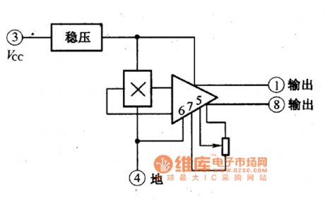
figure:The circuit construction of the double terminal output sensor (View)
View full Circuit Diagram | Comments | Reading(538)
The construction circuit of the single terminal output sensor
Published:2011/6/11 22:42:00 Author:qqtang | Keyword: construction circuit, single terminal output sensor
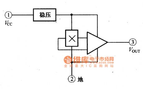
figure:The construction of the single terminal output sensor (View)
View full Circuit Diagram | Comments | Reading(519)
The eyesight feature circuit of the heat releasing electric infrared sensor
Published:2011/6/11 23:41:00 Author:qqtang | Keyword: eyesight feature, infrared sensor
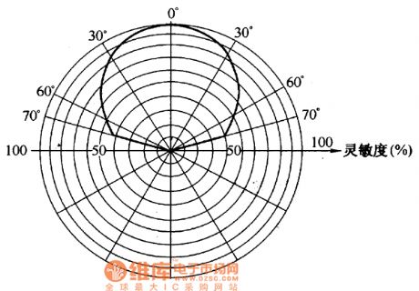
The eyesight feature of the heat releasing electric infrared sensor is shown in the figure.
figure:The eyesight feature of the heat releasing electric infrared sensor is shown in the figure. (View)
View full Circuit Diagram | Comments | Reading(542)
DC high background circuit elimination circuit
Published:2011/5/30 4:52:00 Author:chopper | Keyword: DC, high background circuit, elimination
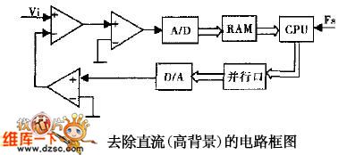
Because the output signal of infrared CCD is of high background and wide dynamic range,it is essential to eliminate the DC high background and automatic gain for smoothing the background noise as well as extracting target signal in this signal's processing circuit.It introduces some normal methods for the application on this signal procession by analyzing the design requirements of infrared CCD signal.At last,it stresses the integration design method on CCD signal processing circuit based on CPLD and VSP3010.
(View)
View full Circuit Diagram | Comments | Reading(370)
TA1229--the SECAM decoding integrated circuit
Published:2011/6/10 0:07:00 Author:qqtang | Keyword: SECAM decoding, integrated circuit
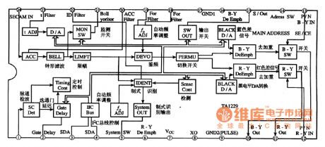
TA1229 is the SECAM decoding integrated circuit produced by Toshiba, which is widely used in local and imported large screen multi-system color TV, such as Changhong NC-6 core and so on.1.function featuresTA1229 consists of ACC amplifier, clock-shape filter, amplitude limiting amplifier, frequency discrimination circuit and aberration switch circuit and other auxiliary function circuits, etc.The internal circuit of auxiliary in shown in figure 1, and this IC circuit completes the SECAM system demodulation under the control the I2C general line.
(View)
View full Circuit Diagram | Comments | Reading(593)
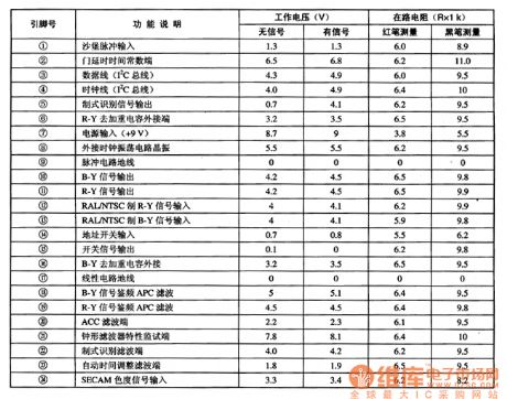
TA7291P--the motor drive integrated circuit
Published:2011/6/9 22:43:00 Author:qqtang | Keyword: motor drive, integrated circuit
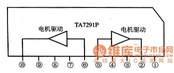
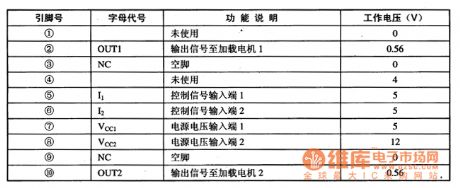
TA7291P is the dual-way motor drive integrated circuit produced by Toshiba, which is widely used in CD, VCD and other players.1.function featuresTA7291P contains two lines of same-function motor drive circuits, decoding drive control circuit, and other affiliated function circuits. The internal circuit of the IC is shown in figure 1.Figure 1. The internal circuit of TA7291P
2.pin functions and dataTA7291P is in 10-pin single line package, whose pin functions and data are listed in table 1.
(View)
View full Circuit Diagram | Comments | Reading(1208)
The infrared lamp controller circuit
Published:2011/6/10 3:19:00 Author:qqtang | Keyword: infrared lamp controller
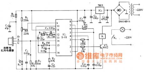
The infrared lamp controller is equipped with a heat releasing infrared sensor as the human body sensor, which can make the lamp controller fulfill functions of lighting with human being coming, cutting off when the people is away , it is especially suitable for hotels, departments, corridors of residential areas and homes.The circuit of the controller is in the figure, which mainly consists of the heat releasing infrared sensors, the infrared process integrated circuit S-01,the control circuit and the power, etc. The integrated circuit IC1 includes the amplifier, comparator, state controller and time delay unit,etc.
(View)
View full Circuit Diagram | Comments | Reading(1385)
| Pages:77/164 At 206162636465666768697071727374757677787980Under 20 |
Circuit Categories
power supply circuit
Amplifier Circuit
Basic Circuit
LED and Light Circuit
Sensor Circuit
Signal Processing
Electrical Equipment Circuit
Control Circuit
Remote Control Circuit
A/D-D/A Converter Circuit
Audio Circuit
Measuring and Test Circuit
Communication Circuit
Computer-Related Circuit
555 Circuit
Automotive Circuit
Repairing Circuit