Automotive Circuit
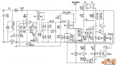
the control circuit of electric fence part 8
Published:2011/6/2 6:20:00 Author:Ariel Wang | Keyword: control, electric, fence | From:SeekIC

After the mains switch S1 gets through, autogenerator works.It generates oscillating impulse voltage on the W2's winding of T1.The oscillating impulse voltage is commutated by VD1 and VD4.It charges C10 by R6.When C10 is full charged and the voltage through C10 reaches +320V,the 2nd-pin of IC1 becomes high level.The autogenerator stops.When the metal wire of the electric fence is not touched by any animals ,IC2 is conducted.C5 is charged.V1 and VU are off condition.The trigger control circuit has no voltage output.VT is not conducted.There is no pulsed high voltage generated on the W4's winding of T2.The alarm circuit doesn't work.VL is not lighted. HA doesn't ring.
Reprinted Url Of This Article:
http://www.seekic.com/circuit_diagram/Automotive_Circuit/the_control_circuit_of_electric_fence_part_8.html
Print this Page | Comments | Reading(3)

Article Categories
power supply circuit
Amplifier Circuit
Basic Circuit
LED and Light Circuit
Sensor Circuit
Signal Processing
Electrical Equipment Circuit
Control Circuit
Remote Control Circuit
A/D-D/A Converter Circuit
Audio Circuit
Measuring and Test Circuit
Communication Circuit
Computer-Related Circuit
555 Circuit
Automotive Circuit
Repairing Circuit
Code: