
Automotive Circuit
Index 73
The FM demodulation circuit
Published:2011/6/20 9:39:00 Author:Seven | Keyword: FM demodulation
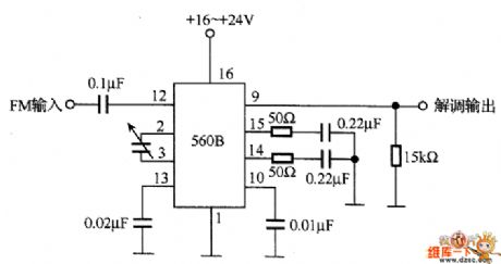
In the figure is the FM demodulation circuit instance, which converts the FM central frequency(10.7 MHz) into the low-frequency signal with 560B. The 560B chip contains the phase comparator, amplifier and voltage control oscillator. When the voltage control oscillator is synchronized with the input signal, the circuit engages in FM demodulation by using the character that the control voltage is proportional to the input signal frequency. When the maximum bias frequency is 75KHz from the central frequency of 10.7MHz, the low-frequency voltage peak value of the corresponding FM wave is 0.21v.
(View)
View full Circuit Diagram | Comments | Reading(1572)
The Jinbei-Sea lion SY6480A2L-ME bus circuit
Published:2011/6/23 2:28:00 Author:qqtang | Keyword: Jinbei, Sea lion
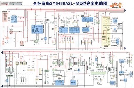
The Jinbei-Sea lion SY6480A2L-ME bus circuit is shown in the figure.
(View)
View full Circuit Diagram | Comments | Reading(506)
The single spot injection circuit of Jinbei-Sea lion SY6480A2F-E bus
Published:2011/6/23 3:29:00 Author:qqtang | Keyword: single spot, injection circuit, Jinbei
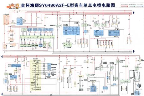
The single spot injection circuit of Jinbei-Sea lion SY6480A2F-E bus is shown as above.
(View)
View full Circuit Diagram | Comments | Reading(538)
MOSFET variable RF gain control circuit
Published:2011/6/16 11:46:00 Author:John | Keyword: variable RF
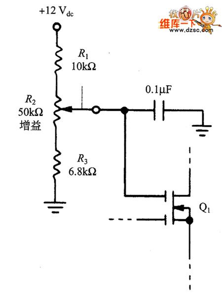
]In the two kinds of MOSFET circuits, the fixed bias network is used to set the gate G2 with a positive DC voltage. It can be replaced with a variable voltage circuit, just as shown in the figure. The potentiometer in the figure can be used as RF gain control device, in order to reduce the gain impact on the strong signal and increase the gain on the weak signal. This design allows the active shunts to prevent strong signal form overloading.
figure: MOSFET variable RF gain control circuit (View)
View full Circuit Diagram | Comments | Reading(800)
The Buick-Royaum, Shanghai, V6 car circuit
Published:2011/6/19 20:24:00 Author:qqtang | Keyword: Buick-Royaum, V6, 3.6L
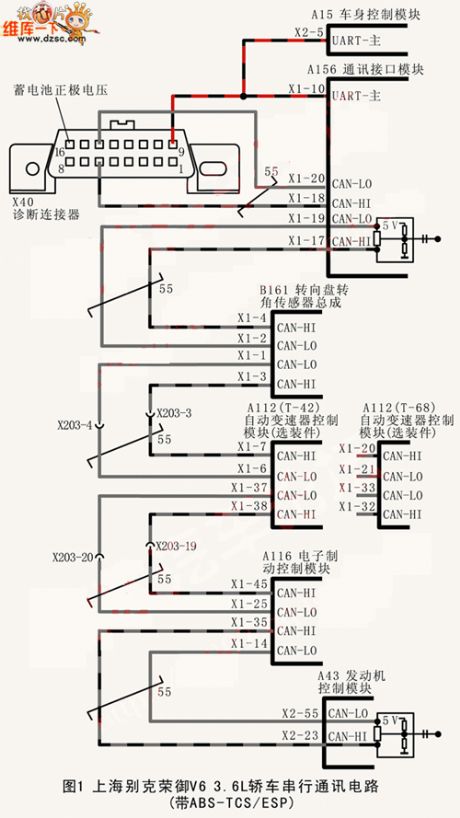
The Buick-Royaum, Shanghai, V6 car circuit is shown in the figure.
Figure 1. The Buick-Royaum, Shanghai, V6 car serial communication circuit (with ABS-TCS/ESP) (View)
View full Circuit Diagram | Comments | Reading(412)
The SBX1483—11/12/51/52 typical application circuit
Published:2011/6/20 11:51:00 Author:Seven | Keyword: typical application circuit
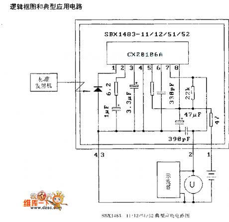
Figure: The SBX1483—11/12/51/52 typical application circuit (View)
View full Circuit Diagram | Comments | Reading(926)
The TA7657P typical application circuit
Published:2011/6/20 22:42:00 Author:Seven | Keyword: typical application circuit
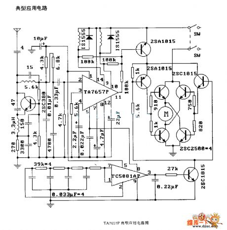
Figure: The TA7657P typical application circuit (View)
View full Circuit Diagram | Comments | Reading(615)
The TA814lS typical application circuit
Published:2011/6/20 22:44:00 Author:Seven | Keyword: typical application circuit

The TA814lS typical application circuit (View)
View full Circuit Diagram | Comments | Reading(440)
The TDA3048 typical application circuit
Published:2011/6/20 22:43:00 Author:Seven | Keyword: typical application circuit
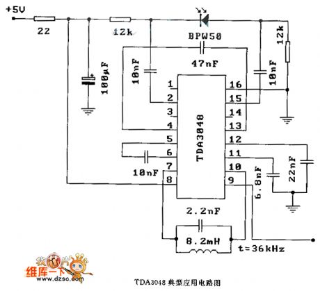
Figure: The TDA3048 typical application circuit (View)
View full Circuit Diagram | Comments | Reading(753)
The 50Hz time based signal generator circuit
Published:2011/6/19 20:07:00 Author:qqtang | Keyword: time based, signal generator
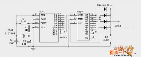
View full Circuit Diagram | Comments | Reading(674)
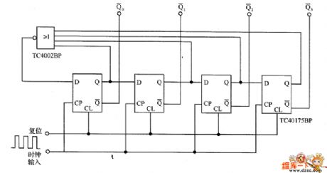
The decimal additive counter circuit
Published:2011/6/21 6:14:00 Author:qqtang | Keyword: decimal, additive counter
In the figure is an example of the decimal additive counter circuit, which splits the input frequency in the decimal method, so it is called the decimal counter, and this is also the basic form of digital counters.
(View)
View full Circuit Diagram | Comments | Reading(459)
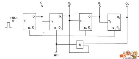
The ring formed counter circuit
Published:2011/6/21 6:08:00 Author:qqtang | Keyword: ring formed, counter
In the circuit is an example of the ring formed counter circuit, the period of the circuit is 4 hours, and the circuit is widely used in all kinds of counter circuit.
(View)
View full Circuit Diagram | Comments | Reading(495)
The pulse accumulation counter circuit
Published:2011/6/21 6:24:00 Author:qqtang | Keyword: pulse, accumulation counter

In the figure is the example of the pulse accumulation counter circuit, which engages in pulse accumulative counting of A terminal, and it is used in the counting of input pulses. The S1~S4 are the reset switch, which are used to set the countered numbers. When the numbers are accumulated to the set values, the circuit is taking action, and the corresponding circuit of the relay control is taking action. If the time pulse in Figure 5-12 is added on A terminal, which can also compose a digital timing circuit base on the power supply frequency.
(View)
View full Circuit Diagram | Comments | Reading(739)
Motor starting circuit
Published:2011/6/21 8:10:00 Author:John | Keyword: Motor
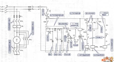
View full Circuit Diagram | Comments | Reading(478)
Motor intermittent start-stop cycling control circuit
Published:2011/6/21 8:13:00 Author:John | Keyword: Motor
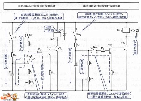
View full Circuit Diagram | Comments | Reading(670)
The TC9149P/TC9150F logic frame circuit
Published:2011/6/20 21:29:00 Author:Seven | Keyword: logic frame circuit
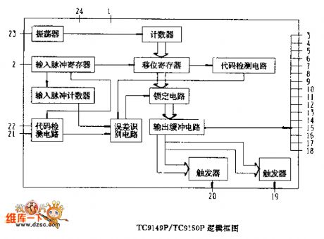
Figure: The TC9149P/TC9150F logic frame circuit (View)
View full Circuit Diagram | Comments | Reading(476)
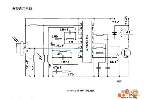
The SNS9201 application circuit
Published:2011/6/20 11:57:00 Author:Seven | Keyword: application circuit
View full Circuit Diagram | Comments | Reading(470)
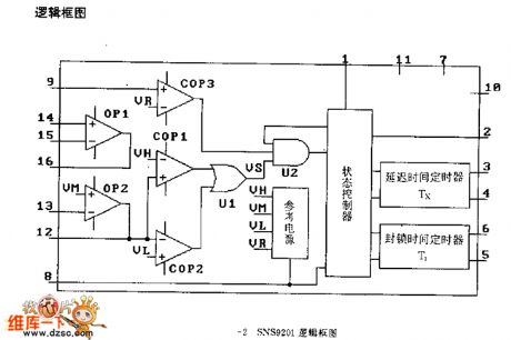
The SNS9201 logic frame circuit
Published:2011/6/20 12:00:00 Author:Seven | Keyword: logic frame circuit
The SNS9201 typical application circuit (View)
View full Circuit Diagram | Comments | Reading(531)
The SUZUKI elevator brake sticking circuit
Published:2011/6/20 22:17:00 Author:Seven | Keyword: SUZUKI elevator, brake sticking
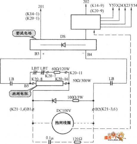
The SUZUKI elevator brake sticking circuit is shown as above. (View)
View full Circuit Diagram | Comments | Reading(509)
The T6A2800 (TV set) logic frame circuit
Published:2011/6/20 11:28:00 Author:Seven | Keyword: logic frame circuit
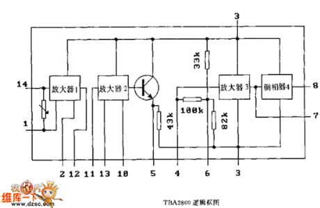
Figure: The T6A2800 (TV set) logic frame circuit (View)
View full Circuit Diagram | Comments | Reading(427)
| Pages:73/164 At 206162636465666768697071727374757677787980Under 20 |
Circuit Categories
power supply circuit
Amplifier Circuit
Basic Circuit
LED and Light Circuit
Sensor Circuit
Signal Processing
Electrical Equipment Circuit
Control Circuit
Remote Control Circuit
A/D-D/A Converter Circuit
Audio Circuit
Measuring and Test Circuit
Communication Circuit
Computer-Related Circuit
555 Circuit
Automotive Circuit
Repairing Circuit