
Automotive Circuit
Index 78
The control circuit of Santana AJR(ZVQS) power jet engine
Published:2011/5/14 10:32:00 Author:Borg | Keyword: control circuit, Santana, power jet engine
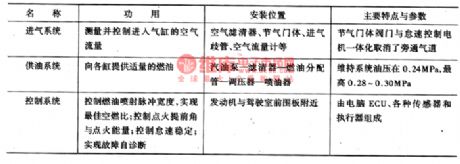
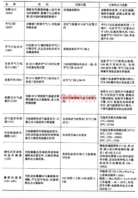


AJR engine is simplified engine without intermediate shafts or electricity distributors, whose igniting order comes from the engine computer(ECU), and ECU delivers the order after getting the signals coming from the engine speed sensor(G28) and camshaft position (Hall) sensor(G40).the construction features of M3.8.2 control systemThe composition, functions, position and features of M3.8.2 power-controlled multiple petrol jet system that is fixed in AJR engine are as shown in Figure 1.Figure 1. The power-controlled petrol jet system of AJR engine
(View)
View full Circuit Diagram | Comments | Reading(573)
The integration design circuit of infrared CCD signal processing
Published:2011/6/3 20:22:00 Author:chopper | Keyword: integration design circuit, infrared CCD signal processing

The CCD signal processing integration design can reduce volume,reduce the noise of circuit and improve signal-to-noise ratio. Due to features of high integration,software programming,easy to modify,completely simulation with CPLD,the CPLD applies to the CCD driver timing and other interface control signals in order to reach the miniaturization,debugging and upgrade of cirucit. (View)
View full Circuit Diagram | Comments | Reading(436)
TA8170--the stereo decoding integrated circuit
Published:2011/6/9 22:36:00 Author:qqtang | Keyword: stereo decoding, integrated circuit

TA8170 is the stereo decoding integrated circuit produced by Toshiba, which is widely used in low-voltage radio circuit as the demodulator of modulate stereo signals, such as walkman and car stereo, etc.1.function featuresTA8170 contains the voltage control oscillator, stereo sound decoing circuit, mixing signal pre-amplifier circuit, stereo/single channel shifting control circuit and other affiliated circuits.2. Pin functions and dataTA8170 is in 10-pin single line package, whose pin functions and data are listed in table 1.
(View)
View full Circuit Diagram | Comments | Reading(567)
TA7792--the FM/AM reception single door integrated circuit
Published:2011/6/9 23:40:00 Author:qqtang | Keyword: FM/AM reception, single door, integrated circuit

TA7792 is the FM/AM reception single door integrated circuit produced by TA7792, which is widely use in low-voltage portable stereo and communication equipment.1.function featuresTA7792 contains FM AGC, self-oscillating, mixing, IF, frequency discrimination circuit; AM AGC, self-oscillating, mixing, IF, detection circuit and other affiliated circuits.2.pin function and dataTA7792 in is 16-pin dual line package, whose pin functions and data are listed in table 1.Table 1. The pin functions and data
(View)
View full Circuit Diagram | Comments | Reading(751)
The TDA1175 single chip field scanning integrated circuit
Published:2011/6/6 12:17:00 Author:qqtang | Keyword: single chip field, integrated circuit


TDA1175 is a single chip field scanning integrated circuit produced by Philips, which is widely used in all kinds of local and imported color screen field scanning circuits.1.pin functionsThe internal circuit of TDA1175 includes field oscillator, sawtooth wave generator, synchronized circuit, voltage steady circuit, retrace generator and power amplifier, etc. The internal circuit of it is shown in Figure 1.As the core of the scanning circuit, TDA1175 has the following characters:(1) it has a separated synchronized amplifier circuit, so it can increase the amplitude of the magnify field;
(View)
View full Circuit Diagram | Comments | Reading(1467)
The integrated chroma signal handle circuit
Published:2011/6/4 8:38:00 Author:qqtang | Keyword: chroma signal


1.function featuresTDA4555 contains ACC amplifier and detection circuit, PAL/NTCC/SECAM recognize and shift control circuit, SECAM modulation circuit, matrix circuit, NTSC hues circuit, 1/2 frequency splitting circuit, channel selecting circuit, color removing circuit circuit, scanning steady circuit, removing circuit, control output circuit and other additional circuits.The internal circuit of TDA4555 is shown in Figure 1.
Figure 1 the internal circuit of TDA4555
2.pin functions and dataTDA4555 is in 28-pin dual in-line package.
(View)
View full Circuit Diagram | Comments | Reading(445)
The integrated circuit of chromatism and basic color signal matrix
Published:2011/6/4 9:01:00 Author:qqtang | Keyword: integrated circuit, chromatism, basic color signal matrix


1.function featuresTDA3504 contains 3 basic color matrix circuit, 3-line signal switch shift circuit, 3-line comparing control circuit, 3-line lightness control circuit, 3-line clamp-on circuit, Y(lightness) signal amplifier circuit, lightness removing motivation circuit, channel-selecting and amplitude and other additional circuit. The internal circuit of TD3504 is shown in Figure 1.Figure 1. The internal circuit of TDA3504
2.pin functions and dataTDA3504 is in 20-pin dual in-line package.
(View)
View full Circuit Diagram | Comments | Reading(483)
The TDA1675A field scanning integrated circuit
Published:2011/6/5 3:46:00 Author:qqtang | Keyword: field scanning, integrated circuit


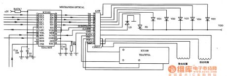
TDA1675A is a field scanning integrated circuit produced by Philips, which is widely used in local and imported TV screens, such as EMC color TV screens, etc.1. Function features TDA1675A contains a synchronize circuit, field oscillator, field sawtooth wave generator, field pre-motivation circuit, pulse removing generator, heat protection circuit, OTL dual power supply output stage and other additional circuits, etc. The internal circuit of it is shown in Figure 1.Figure 1. The internal circuit and typical application circuit of TDA1675A
(View)
View full Circuit Diagram | Comments | Reading(2089)
TDA1302T--the integrated circuit of RF signal preset amplifiers
Published:2011/6/5 5:42:00 Author:qqtang | Keyword: integrated circuit, RF signal
TDA1302T is an integrated circuit of RF signal preset amplifiers produced by Philips, which is widely used in all kinds of local and imported disc players.1.pin functions and dataTDA1302T is in 24-pin dual in-line package, whose pin functions and data are listed in Table 1.Table 1. pin functions and data of TDA1302T
2.typical applications circuitThe typical application circuit of RF amplifier, which consists of TDA1302T, is shown in Figure 1.Figure 1. The typical applications circuit of TDA1302T
(View)
View full Circuit Diagram | Comments | Reading(1140)
TDA1301T--the servo processing integrated circuit
Published:2011/6/5 5:32:00 Author:qqtang | Keyword: servo processing, integrated circuit
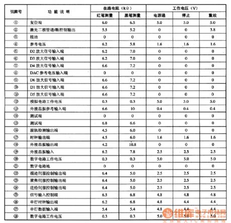
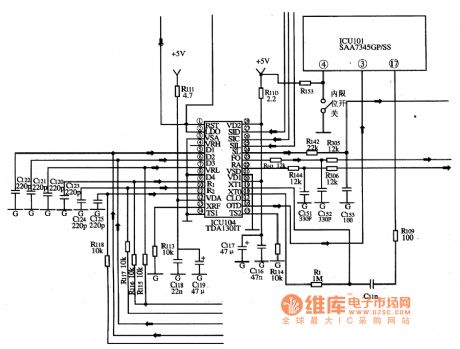
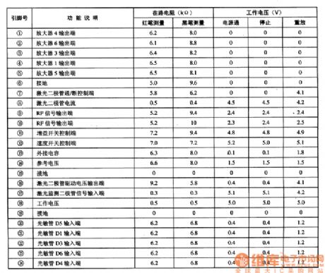
TDA1301T is the servo processing integrated circuit produced by Philips, which is widely used in all brands of disc players, such as Malata and Shinco, etc.1.function featuresTDA1301T includes tracking servo, focus servo, feed servo control circuit, laser diode cutting control circuit, serial clock and data signal processing circuit, off-route detection circuit, reset circuit and other additional function circuits.2.pin functions and dataTDA1301T is in 28-pin dual in-line package.
(View)
View full Circuit Diagram | Comments | Reading(1357)
The reaper warehouse full reminder circuit (2)
Published:2011/6/5 5:59:00 Author:qqtang | Keyword: reaper warehouse, full reminder
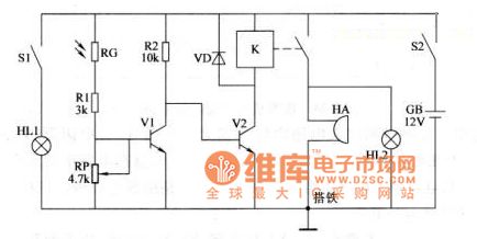
Working principle
In the circuit, the photoelectric detection amplifier consists of indicator HL1, lamp switch S1, LDR resistor RG, resistor R1 and R2, potentiometer RP and NPN v1; the acousto-optic siren circuit consists of NPN V2, relay K, diode VD, indicator HL2 and buzzer HA. When using it, fix the reminder circuit in a small control box, RG and HL on the front-end plate of the control box, S1, S2 and HA on the rear board of the control box, locate HL2 in a place which the working man can easily see.
(View)
View full Circuit Diagram | Comments | Reading(533)
Multifunctional Motor Protector (2)
Published:2011/5/25 6:18:00 Author:Sue | Keyword: Multifunctional, Motor, Protector
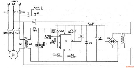
When the motor is working well, TA's induced voltage is low, IC's 6 pin's voltage is lower than 2Vcc/3, 3 pin outputs low level. K is not connected.
When L2 or L1 lacks phase, L3's phase current will be larger. TA's induced voltage will be lager. IC's 6 pin's voltage is higher than 2Vcc/3. 3 pin will have low level. KM is released and M stops working.
When the motor is overload, L1-L3 will have larger current. When the current reaches 1.2 times rated current, IC's 6 pin will have a voltage higher than 2Vcc/3. M will stop working. (View)
View full Circuit Diagram | Comments | Reading(489)
Multifunctional Motor Protector (3)
Published:2011/5/25 6:23:00 Author:Sue | Keyword: Multifunctional, Motor, Protector
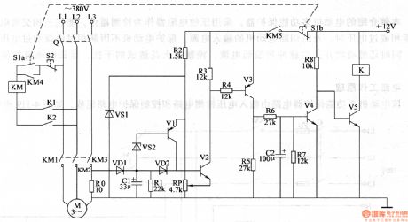
When S1 is pushed, V5 is connected and K is connected. K1 K2 are connected and M begins to work. The current detection control circuit begins to work.
When the motor works well, RO's voltage is low, V1-V4 are disconnected and V5 is connected.
When the motor is overloaded or the voltage is low, RO's voltage will be higher. V2-V4 will be connected and V5 is disconnected. K is released and K1 K2 are disconnected. M stops working. (View)
View full Circuit Diagram | Comments | Reading(542)
Multifunctional Motor Protector (1)
Published:2011/5/25 6:13:00 Author:Sue | Keyword: Multifunctional, Motor, Protector
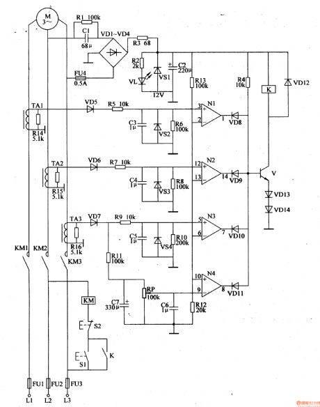
When the motor works well, N1-N3's in-phase input terminals have higher voltage than reference voltage. N4's opposite phase has a lower voltage than the reference voltage. N1-N4 output high level. VD8-VD11 are disconnected. V,VD13,VD14 are connected.
When the motor doesn't work well, V is disconnected and K is released.KM is released. M's working power will be cut off.
When the motor is overload, W's opposite phase will have a higher voltage than the reference voltage. N4 outputs low level and VD11 is connected, V is disconnected. K and KM are released. The motor's working power will be cut off. (View)
View full Circuit Diagram | Comments | Reading(417)
Common Electrical Motor Controlled Circuit (5)
Published:2011/5/27 6:06:00 Author:Sue | Keyword: Common, Electrical, Motor, Controlled

When the circuit is set up, S1 and s2, s3 and s4, s5 and s6 will be put in 3 controlling site. Push s1 in the first site, KM will be connected, M will start working. Push s2 then, KM is released and M stops working. As this principle, push s2 in the second site or push s5 in the third site, KM will be connected and M starts working. Push S4 or S6, KM will also be released and M stops working.
This makes the 3-site control of the motor. (View)
View full Circuit Diagram | Comments | Reading(491)
Common Electrical Motor Controlled Circuit (4)
Published:2011/5/27 6:00:00 Author:Sue | Keyword: Common, Electrical, Motor, Controlled

When Q and S1 are connected, KM KT1 are connected. M begins to work. After a while, KT1's time delay connected contactor is connected and KA KT2 are connected. KM KT1 are released. M stops working. After a while, KT2's time delay disconnected contactor is disconnected and M is released. M and KT1 are connected. M starts working again.
When KM is released and M stops working, push button S2, KM will be connected and M will start to work. (View)
View full Circuit Diagram | Comments | Reading(565)
Common Electrical Motor Controlled Circuit (3)
Published:2011/5/27 5:56:00 Author:Sue | Keyword: Common, Electrical, Motor, Controlled

S1 is starting button, S2 is stop button, S3 is jogging control button.
When the circuit is started, Q is connected. S1 is pushed and KM is connected. KM1 KM2 are connected. M begins to work. When S1 is released, KM is still connected.
When we stop the circuit, S2 is pushed and KM is released. M stops working.
When jogging control is needed, S3 is pushed, KM is connected. M begins to work. When S3 is released, KM is released and M stops working. (View)
View full Circuit Diagram | Comments | Reading(2916)
TDA4859--the integrated circuit of power supply control and scanning signal handling
Published:2011/6/4 8:10:00 Author:qqtang | Keyword: power supply control, scanning signal handling

1.function features TDA4859 contains I2C general connector circuit, power supply fault amplifier circuit, primary current detect circuit of power supply, the output circuit of power supply motivation pulse, the output circuit of motivation circuit, the adjusting circuit of HAFC and distortion, field oscillate and motivate circuit, the handle circuit of travel-field synchronization signal, and travel-field amplitude compensation circuit, etc.2.pin functions and dataTDA4859 is in 32-pin dual-line package, whose pin functions and data are seen in Table 1.
(View)
View full Circuit Diagram | Comments | Reading(1032)
TDA4565--the brightness delaying integrated circuit
Published:2011/6/5 3:15:00 Author:qqtang | Keyword: integrated circuit, brightness delaying


TDA4565 is he brightness delaying integrated circuit produced by Philips, which is widely used in local and imported large screen color TV.1. Function features TDA4565 contains two lines of differentiation and integration handle circuits of chromatism (R-Y) and (B-Y) signals, switch storage circuits, clamp circuits, time delay circuits, throttle valve circuits and so on.
2.pin functions and dataTDA4565 is in 18-pin dual in-line package, whose pin functions and data are listed in Table 1.Table 1 the pin functions and data of TDA4565
(View)
View full Circuit Diagram | Comments | Reading(557)
TC9083N and TC9083F--the integrated circuit of single chip PIP control
Published:2011/6/6 23:27:00 Author:qqtang | Keyword: integrated circuit, single chip, PIP control
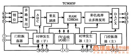
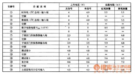
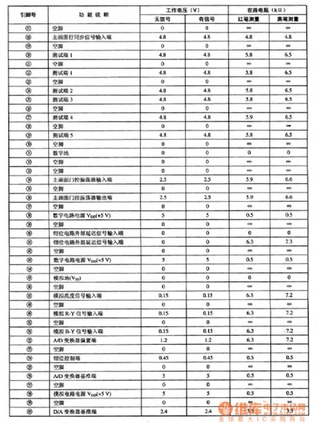
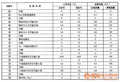
Both TC9083N and TC9083F are integrated circuitsof single chip PIP control produced by Toshiba, which is widely used in local and imported large screen PIP color TV, such as Changhong NC-6 cores, KONKA T2988/3488/3888 color TV and so on .1.function featuresThe internal circuits of TC9083N and TC9083F are almost the same but the package. Take TC9083F as an example, it contains sub-circuits, such as a line of 6 bit A/D converter, 3 lines of 12k bit dynamic storage, clock generator, PIP controller and so on, which is suitable for many kinds of signal PIP processing.
(View)
View full Circuit Diagram | Comments | Reading(505)
| Pages:78/164 At 206162636465666768697071727374757677787980Under 20 |
Circuit Categories
power supply circuit
Amplifier Circuit
Basic Circuit
LED and Light Circuit
Sensor Circuit
Signal Processing
Electrical Equipment Circuit
Control Circuit
Remote Control Circuit
A/D-D/A Converter Circuit
Audio Circuit
Measuring and Test Circuit
Communication Circuit
Computer-Related Circuit
555 Circuit
Automotive Circuit
Repairing Circuit