Automotive Circuit
Multifunctional Motor Protector (1)
Published:2011/5/25 6:13:00 Author:Sue | Keyword: Multifunctional, Motor, Protector | From:SeekIC

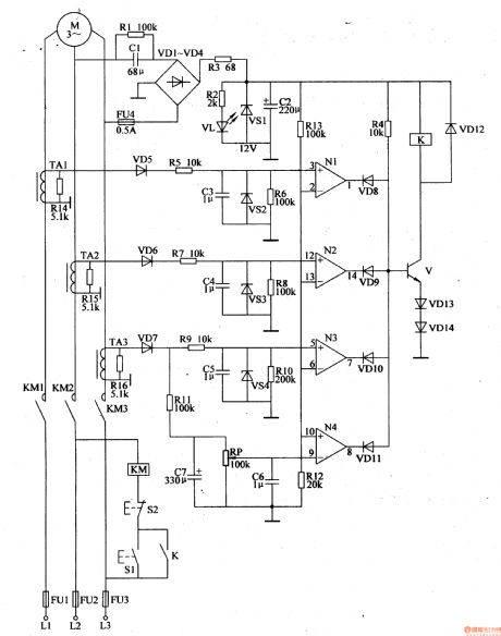
When the motor works well, N1-N3's in-phase input terminals have higher voltage than reference voltage. N4's opposite phase has a lower voltage than the reference voltage. N1-N4 output high level. VD8-VD11 are disconnected. V,VD13,VD14 are connected.
When the motor doesn't work well, V is disconnected and K is released.KM is released. M's working power will be cut off.
When the motor is overload, W's opposite phase will have a higher voltage than the reference voltage. N4 outputs low level and VD11 is connected, V is disconnected. K and KM are released. The motor's working power will be cut off.
Reprinted Url Of This Article:
http://www.seekic.com/circuit_diagram/Automotive_Circuit/Multifunctional_Motor_Protector_1.html
Print this Page | Comments | Reading(3)

Article Categories
power supply circuit
Amplifier Circuit
Basic Circuit
LED and Light Circuit
Sensor Circuit
Signal Processing
Electrical Equipment Circuit
Control Circuit
Remote Control Circuit
A/D-D/A Converter Circuit
Audio Circuit
Measuring and Test Circuit
Communication Circuit
Computer-Related Circuit
555 Circuit
Automotive Circuit
Repairing Circuit
Code: