
Automotive Circuit
Index 75
The audio noise generator
Published:2011/6/16 0:18:00 Author:Borg | Keyword: audio noise generator
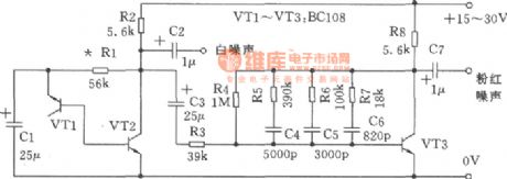
In the figure is a simple circuit which can generate white and pink noises. The voltage steady pipe is the crystal triode VTI, which generates wide-band noises in the Zener breakdown state. After being amplified by VT2, a white noise of 150mV or so is output by capacitor C2. To convert the white noise into pink noise, we use a filter net, each frequency doubler of this filter provides a 3dB reduction. As the filter reduces much of the noise, so we need an amplifier to recover the output LEV. (View)
View full Circuit Diagram | Comments | Reading(1331)
The video boosting circuit
Published:2011/6/16 0:07:00 Author:Borg | Keyword: boosting circuit
View full Circuit Diagram | Comments | Reading(595)
The frequency synthesizer formed by CD4046
Published:2011/6/16 5:40:00 Author:Borg | Keyword: frequency synthesizer

The so-called frequency synthesis means converting a certain reference frequency ^ into a series of new frequencies like fo1、fo.....fon. These new frequencies have the same stability as the former reference frequency. If we put a frequency splitter, whose splitting constant is fixed, between the 3-pin and 4-pin of CD4046, a new frequency doubler with the fixed multiple is formed. If we insert a multi-stage splitter with adjustable constants, then a multi-stage adjustable doubler is formed, which is the frequency synthesizer . In the figure is a frequency synthesizer made of CD4017. (View)
View full Circuit Diagram | Comments | Reading(6028)
The precise frequency synthesizer composed of CD4046
Published:2011/6/16 5:50:00 Author:Borg | Keyword: frequency synthesizer
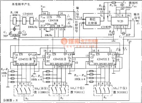
In the figure is a practical frequency synthesizer, which is equipped with a highly stable quartz crystal oscillator, and it generates a 100KHz rectangle pulse which is split into 1KHz pulse by the splitter as the reference frequency. The synthesizer is preset by a switch, which can output 999 kinds of reference frequencies that are 1~999kHz with the interval of 1KHz. The synthesizer is very useful.
(View)
View full Circuit Diagram | Comments | Reading(4176)
The 60Hz time-based generator composed of MM5369
Published:2011/6/15 21:23:00 Author:Borg | Keyword: time-based generator
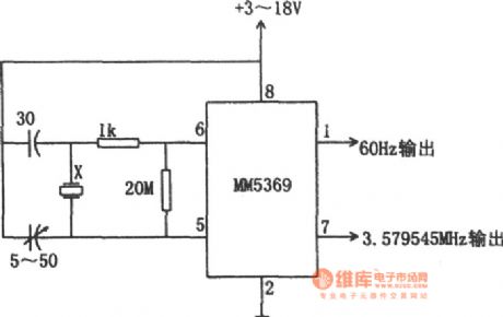
In the figure is the 60Hz time-based generator composed of MM5369. In many conditions, 60Hz has been a reference frequency, such as electric clock, timer and controller, etc, and all of their reference frequencies are 60Hz. So a independent 60Hz signal source is often in need, which is used in portable or battery power supplies for test or development. This circuit is formed by the integrated TV MM5369 time-based generator. The device needs external crystal which is cut according to the standard color synchronized signal frequency of standard 3.57954MHz. (View)
View full Circuit Diagram | Comments | Reading(3558)
The connector circuit of the Hall switch integrated sensor
Published:2011/6/11 22:39:00 Author:qqtang | Keyword: connector circuit, Hall switch integrated sensor
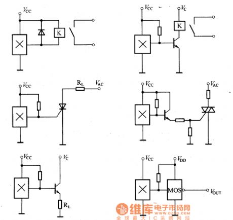
The output voltage and the external magnetic power of the Hall switch integrated sensor are in the linear ratio relationship. This kind of sensors usually consists of Hall parts and amplifiers. When there is an external field, the Hall part is generating a Hall voltage which is in linear relationship with the field power, the voltage is output after being magnified by the amplifier. In the practical circuit designing, to improve the funciton of the sensor, there is always a voltage steady circuit, a current amplifying output stage, a dysfunction adjusting circuit and a linearity adjusting circuit, etc.
(View)
View full Circuit Diagram | Comments | Reading(439)
The the working feature curve circuit of the dual stable state Hall switch integrated sensor
Published:2011/6/11 22:28:00 Author:qqtang | Keyword: working feature curve, stable state, Hall switch integrated sensor
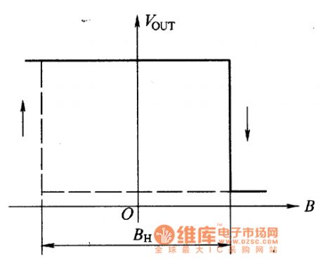
SL3075 Hall switch integrated sensor is a dual stable state sensor, which is also called lock-key sensor, its working feature curve is shown in the figure. When the external magnetic field power is over the working point, the output is in the conducting state. And when the magnetic field is disappearing, the output remains the same, if we want to cut off the output, we should impose an inverting field.
Figure: The the working feature curve of the dual stable state Hall switch integrated sensor (View)
View full Circuit Diagram | Comments | Reading(429)
The working character curve circuit of the Hall switch integrated sensor
Published:2011/6/11 22:21:00 Author:qqtang | Keyword: working character curve, Hall switch integrated sensor
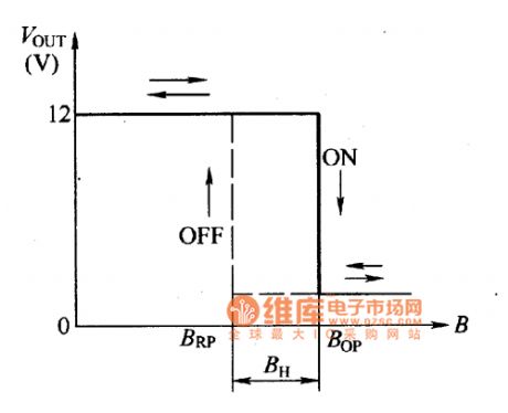
The working character of the Hall switch integrated sensorThe working character of the Hall switch integrated sensor is shown in the figure. Seeing from the working character curve, the working character is with certain magnetic lag (BH), which is good for the reliability of the switch action. In the firgure, Bop is the magnetic sensing power at the working point ON , the RBP is the power of the releasing point OFF .The working character curve of the Hall sensor indicates the relationship between the external magnetic field and the sensor output LEV.
Figure: The working character curve of the Hall switch integrated sensor (View)
View full Circuit Diagram | Comments | Reading(434)
The outline and typical application circuit of the Hall switch integrated sensor
Published:2011/6/11 22:06:00 Author:qqtang | Keyword: typical application circuit, Hall switch integrated sensor
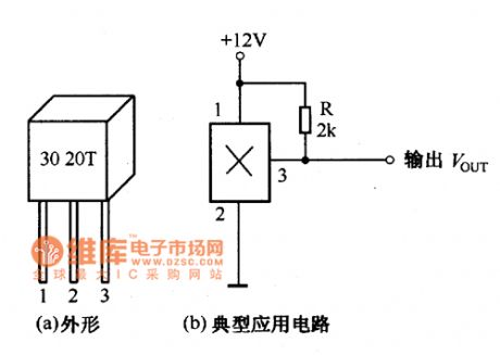
The outline and typical application circuit of the Hall switch integrated sensor are shown in the figure.
figure:The outline and typical application circuit of the Hall switch integrated sensor (View)
View full Circuit Diagram | Comments | Reading(437)
The wide wavelength random noise generator
Published:2011/6/15 2:52:00 Author:Borg | Keyword: wide wave, noise generator
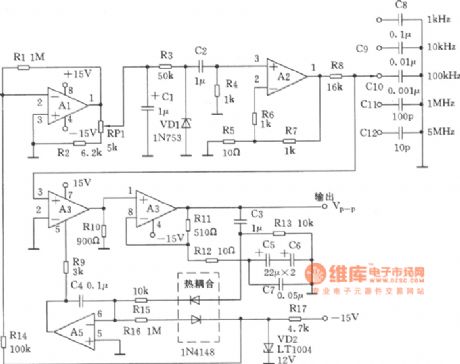
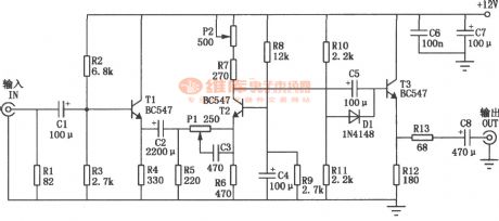
In the figure, the circuit can provide a noise source whose RMS amplitude is adjustable, the band width can be adjusted. The RMS output of his circuit is 1kHz~5MHz, and the band width can reach 300mY, the frequency band has 5 gears to choose from.
(View)
View full Circuit Diagram | Comments | Reading(620)
The circuit of IC oscillating circuit-inductance three-point oscillator
Published:2011/6/13 21:49:00 Author:Seven | Keyword: IC oscillating circuit, inductance three-point oscillator
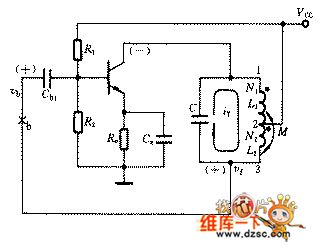
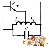
(1) the formation of inductance three-point oscillatorIn figure 1 is the principle diagram of the inductance three-point oscillator circuit. Seeing from the circuit, we know that the inductor of LC parallel resonance circuit has a front-end point, a middle point and a tail point, whose AC circuit connects with the collector electrode of the amplifier circuit, emitter(ground) and basic pole respectively, the feedback signal is from the voltage on the inductor L2, therefore, we conventionally call the circuit in Figure 1 the inductance three-point LC oscillating circuit, or the inductance feedback oscillating circuit.
(View)
View full Circuit Diagram | Comments | Reading(752)
The dual-way video amplifier circuit composed of MAX457CPA
Published:2011/6/15 3:17:00 Author:Borg | Keyword: video amplifier, dual-way

View full Circuit Diagram | Comments | Reading(594)
Electronic Thermostat Of The Automobile Air-conditioner
Published:2011/5/18 8:47:00 Author:Felicity | Keyword: Automobile Air-conditioner, Thermostat,
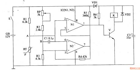
When the temperature rises in the car, the resistance of RT falls, and then the potential of A drops. When the potential of A is lower than the potential of B, the outputs of N2 and N1 are both high level, and then V is on, and the normally open contact of K is switched on. Then the clutch of air conditioner is on, then the compressor works. The air conditioning system begin to refrigerates .As the temperature falls in the car, the resistance of RT rises, and then the potential of A rises. When the potential of A is higher than the potential of B, the outputs of N2 and N1 are both low level, and V cutoff .The normally open contact of K releases, then the clutch of air conditioner is off. The refrigeration system stops work. (View)
View full Circuit Diagram | Comments | Reading(3239)
Storage Battery Voltage Monitor (2)
Published:2011/5/16 4:47:00 Author:Sue | Keyword: Storage, Battery, Voltage, Monitor
Here we will introduce a storage battery voltagle monitor circuit composed of digital integrated circuit CD4011. The drivers can know whether the battery voltage is proper by observing the lights on the monitor. When the voltage is proper, the light doesn't work. When the voltage exceeds a certain value, the light will keep on working. When the voltage is reduced to a certain value, the lightwill betwinkling, warning the driver of the low voltage which need charging.
Working Principle:
As seen in the figure 7-49, the storage battery monitor circuit consists of four-NOT gate integrated circuit IC's 2 inside NOT gate circuit D1,D2 and resistor R1-R5, potentiometer RP1,RP2, capacitor C, transistor V, indicating light HL.
When the voltage is proper, IC's 4 pin outputs low level, and V is disconnected, HL doesn't work.
When the voltage is higher than the proper one, IC's 4 pin outputs low level, and V is connected, HLkeeps on working.
When the voltage is lower than the proper one, IC's4 pin outputssquare form pulse, and V is connected and disconnected from time to time, HL keeps twinkling. (View)
View full Circuit Diagram | Comments | Reading(668)
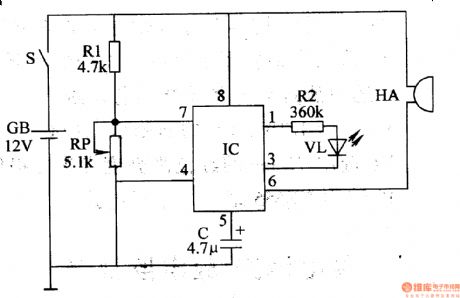
Electronic Mouse Killer (3)
Published:2011/5/17 5:01:00 Author:Sue | Keyword: Electronic, Mouse Killer

When there is 220V voltage, T's secondary winding W2 will generate hundreds of induced voltage. The voltage will be sent to VT's positive pole. T1's W3 will generate 6V alternating voltage, which will be sent to V1's emitting pole and K's magnetic coil.
When mouse comes to eat the food hung on the pole, V1 will be connected and output high level, which will be sent to VT, making VT connected. The pulse high voltage will kill the mouse. At the same time, V1's high level will be sent to V2's base through VD6 and R3, making V2 and K connected. So the normally open contactor will be connected,and force HAtomake a warning sound. (View)
View full Circuit Diagram | Comments | Reading(1636)
Single-Phase Motor Controlled Circuit
Published:2011/5/16 3:12:00 Author:Sue | Keyword: Single-Phase, Motor, Controlled

When Q1 and Q2 are connected, push the starting button S2. The 220V ac voltage will go to KM2, making KM2 connected, and the motor M will begin to work. When S2 is released, KM2 is still connected. When push S1, KM2 will be disconnected and M stops working.
When S3 is connected, KM2 will be connected and M will rotate in a reverse direction.
When there is too much voltage and current on M, Q1 will be disconnected automatically to protect M. If KM1 or KM2's coils are short, Q2 will be disconnected automatically. (View)
View full Circuit Diagram | Comments | Reading(5670)
Second order active low-pass filter circuit
Published:2011/6/10 7:14:00 Author:chopper | Keyword: Second order, active low-pass filter
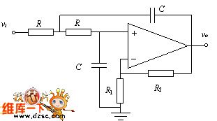
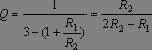
Quality factor indicates the state of bandpass filter. General requirement Q = 0.707.Then,we can get the following formula:
Cut-off frequency w0 =w =1/RC,that is:f =1/2pRC (View)
View full Circuit Diagram | Comments | Reading(1151)
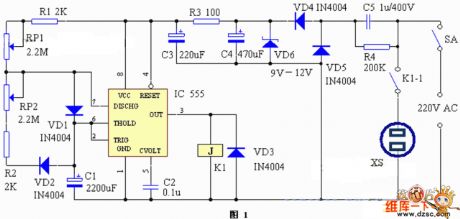
repeated timing circuit
Published:2011/5/16 2:41:00 Author:Christina | Keyword: repeated, timing
Working principle:
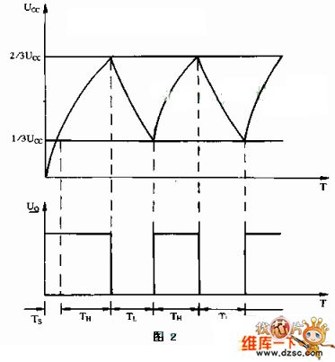
The repeated timing circuit is as shown in figure 1. The no steady-state circuit is composed of the IC555 RP1, R1, RP2, R2, VD1, VD2 and C1, the output port's (pin-3) high-to-low level conversion time is decided by the capacitor C1's charging-discharging time, and this is the opening and closing time of the electric appliance which is controlled by the circuit. This shows that we just need to adjust C1's charging-discharging time, so we can adjust the opening and closing time of the electric appliance which is controlled by the circuit. In this circuit, we can add the diodes VD1 and VD2 to ensure the C1's charging time and discharging time can be adjusted.
In this circuit's working process, pin-2 and pin-3's voltage changing process is as shown in figure 2. TH is the working time of the controlled electric appliance, TL is the rest time of the electric appliance.
Component selection:
In this circuit, the IC can chooses the time-base circuit such as the LM555, NE555, MA555 and 5C1555; relay K1 can choose the small and medium-size power relay with the Rated working voltage of 9V to 12V; the diode VD6 can choose the diode with 12V voltage value such as 2DW21.etc. (View)
View full Circuit Diagram | Comments | Reading(557)
Tianjin Toyota Vios circuit
Published:2011/6/1 21:12:00 Author:Christina | Keyword: Tianjin, Toyota, WeiChi

The Tianjin Toyota Vios circuit is as shown:
(View)
View full Circuit Diagram | Comments | Reading(1917)
Oscillator phase-shifting circuit
Published:2011/5/19 0:43:00 Author:John | Keyword: Oscillator phase-shifting

Oscillator phase-shifting circuit is shown below.
(View)
View full Circuit Diagram | Comments | Reading(432)
| Pages:75/164 At 206162636465666768697071727374757677787980Under 20 |
Circuit Categories
power supply circuit
Amplifier Circuit
Basic Circuit
LED and Light Circuit
Sensor Circuit
Signal Processing
Electrical Equipment Circuit
Control Circuit
Remote Control Circuit
A/D-D/A Converter Circuit
Audio Circuit
Measuring and Test Circuit
Communication Circuit
Computer-Related Circuit
555 Circuit
Automotive Circuit
Repairing Circuit