
Automotive Circuit
Index 61
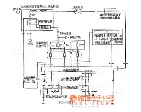
Accord 2003 vehicle cruise control circuit diagram
Published:2011/6/26 22:40:00 Author:Ecco | Keyword: Accord 2003 , vehicle , cruise control
View full Circuit Diagram | Comments | Reading(624)
BENZ 560SL ABS system circuit
Published:2011/7/4 2:05:00 Author:Christina | Keyword: BENZ, ABS, system circuit
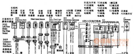
BENZ 560SL ABS system circuit
(View)
View full Circuit Diagram | Comments | Reading(569)
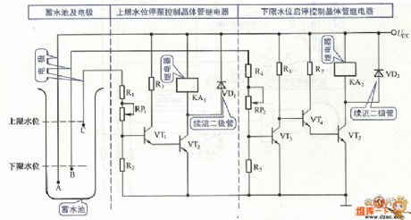
Pump starting-stoping control circuit
Published:2011/7/4 0:22:00 Author:John | Keyword: Pump
View full Circuit Diagram | Comments | Reading(469)
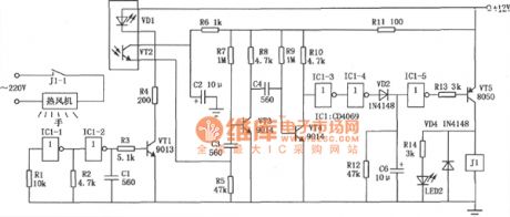
Infrared remote control heat release column circuit
Published:2011/6/27 22:19:00 Author:chopper | Keyword: Infrared, remote control, heat release, column circuit
View full Circuit Diagram | Comments | Reading(498)
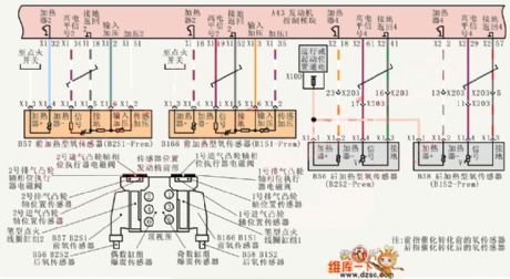
Shanghai Buick Royaum V63.6L car oxygen sensor circuit diagram
Published:2011/6/24 4:19:00 Author:Nicole | Keyword: Shanghai Buick Royaum, car, oxygen sensor
View full Circuit Diagram | Comments | Reading(499)
The non-source current/voltage separation amplifier circuit of transformer coupling type
Published:2011/7/1 21:56:00 Author:Borg | Keyword: amplifier circuit, transformer coupling
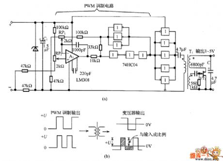
In the figure is the non-source current/voltage separation amplifier circuit of transformer coupling type. In the circuit, the bias branch of the input signal is taken as the power supply of the circuit, the input signal is a DC current of 4~20mA. The circuit is in PWM modulation, the total current consumption is under 4mA, and the circuit has no power for transformer coupling.
PWM modulated signal is split in two signals of the same size by the transformer, see as the sloped line part of figure (b). The single peak value and the input signal of pulse waveform are in the positive ratio. (View)
View full Circuit Diagram | Comments | Reading(948)
The transformer coupled current/current separation amplifier circuit
Published:2011/7/1 22:07:00 Author:Borg | Keyword: transformer, amplifier circuit, current separation
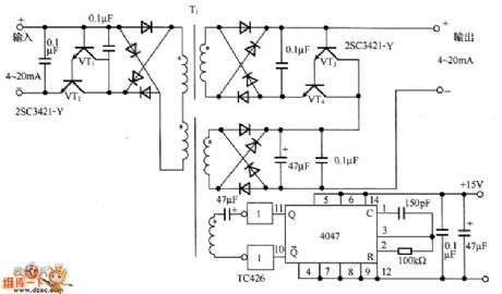
In the figure is the transformer coupled current/current separation amplifier circuit. In the circuit, the Darlington-connected transistors (VT1 and VT2) are as the current buffering circuit, which uses the DC/DC converter to convert the primary current signal of the transformer T1 into the AC signal, and then it is sent to the secondary stage. The secondary stage converts the diode bridge current into the DC current signal. As the signal is the current signal, which is not affected by the UF of the diode. The secondary stage also adopts the transistors (VT3 and VT4) as the buffer.
(View)
View full Circuit Diagram | Comments | Reading(639)
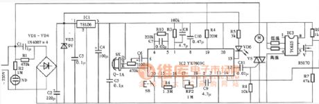
the circuit of the temperature and humidity automatic controller (1)
Published:2011/6/21 7:04:00 Author:Ariel Wang | Keyword: temperature , humidity, automatic controller
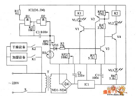
When the value of temperature and humidity in monitor room is beyond the set value,the voltage of IC2's pin-6 is lower than the voltage of pin-5. The in-circuit of IC2 overturns.Pin-3 outputs high level.K is pulled over.The normally open contacts K1-1 and Kl-2 are connected.The discharge fan and the ventilator get to work until the value of temperature and humidity in monitor room is within the set value.RP1 is used to set the value of temperature in monitor room.RP2 is used to set the value of humidity in monitor room.When you adjust it,you should put S at the position of adjusting .Then you should adjust the resistence of RP1 and RP2.When you use it,you should put S at the position of automatic .
(View)
View full Circuit Diagram | Comments | Reading(457)
the circuit of the multifunctional protector for electric motor(3)
Published:2011/6/22 7:38:00 Author:Ariel Wang | Keyword: multifunctional protector, electric motor(
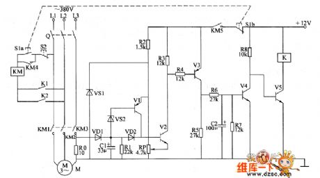
When 51 gets through,V5 is saturated to conduct.K is pulled in.The normally open contacts K1 and Φ are connected.KM acts.Then the electric motor M works.At the same time,the current detect and control circuit is conducted to work.When the electric motor is working,the voltage of R0 is low.VI~V4 are stopped.V5 stays conducted.When the electric motor is overload or the working voltage is low,the voltage of R0 increases.V2~V4 are conducted.V5 is stopped.K is released.The normally open contact K1 is disconnected.KM is power down.So KM is released.The electric motor M is power down.So it is stopped.
(View)
View full Circuit Diagram | Comments | Reading(417)
the circuit of the multifunctional protector for electric motor(2)
Published:2011/6/23 6:12:00 Author:Ariel Wang | Keyword: multifunctional protector , electric motor
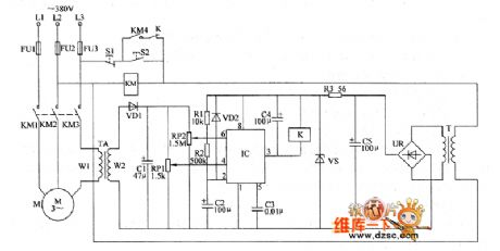
When there is phase lacking in L1 and L2,the current of L3 will increase rapidly(about 1.73 times normal current).The induced voltage of TA's winding on W2 is increased.The voltage of IC's pin-6 is higher than 2Vcc/3.The high level of pin-3 becomes low level.K is pulled in.The normally closed contacts are disconnected.KM is released as it is power down.The working voltage of electric motor M is cut off by the normally open contacts KM1~KM4.If there's phase lacking in L3,there will be no the induced voltage from TA.It is similar as the low level goes to pin-4 of IC .Pin-3 of IC outputs low level.K is pulled in.KM is released.Electric motor M stops working.
(View)
View full Circuit Diagram | Comments | Reading(362)
the circuit of the temperature controller(13)
Published:2011/6/25 20:48:00 Author:Ariel Wang | Keyword: temperature controller
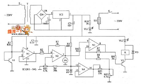
When then environment temperature detected by V1 is lower than the temperature set by RP3,N3 outputs low level(about 0.65V).V2 is saturated to conduct.K is conducted to pull in.VL2 is lighted.The electric heater is conducted to work.The environment temperature goes up slowly.When the temperature rises to the set temperature,N3 outputs low level(about 7.7V).V2 is stopped.K is released.VL2 dies out.The electric heater EH is power off.So it stopes heating.Soon after,the environment temperature goes down slowly,when the temperature goes down to the set temperature.K is pulled in.EH is conducted to heat.It goes on and on.So the temperature in the controlled place is around the set temperature.
(View)
View full Circuit Diagram | Comments | Reading(430)
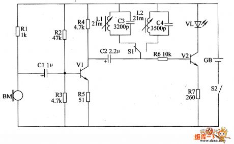
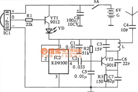
the circuit of the animal littering announcer (1)
Published:2011/6/28 6:06:00 Author:Ariel Wang | Keyword: animal baby, announcer
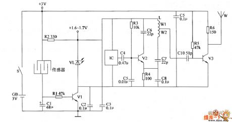
When the animals have babies,the resistence between two crossed electrodes of the comb-like sensor become small.V1 is saturated to conduct.VL is lighted.The +3V voltage is current limited by R2.It is connected with VL and V2 in series.And it is regulated by them.Then it provides IC and the high frequency oscillator (consists of R3,R3,C4~C8,L1 and V2) 1.6~1.7V DC working voltage.IC outputs the acoustics signal.It is modulated by the high frequency oscillator.And it is power amplified by V2.Then it is emitted by antennas W to the sky.The feeder can recieve the alarm signal of having animal babies by FM in a distance.
(View)
View full Circuit Diagram | Comments | Reading(399)
the circuit of the chickling hatching announcer(3)
Published:2011/6/28 5:59:00 Author:Ariel Wang | Keyword: chickling, hatching, announcer
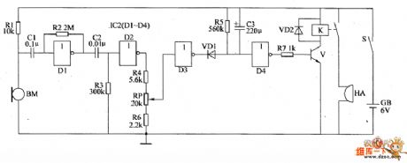
When the mains switch gets through,the whole control circuit is at the state of waiting.The not gate circuit D4 outputs low level.The transistor V is stopped.The relay K is released.HA doesn't give a sound.When there are baby chicken ,BM will convert the sound of the chickling to the electric signal.The electric signal is amplified by not gate D1,reversal processed by D2.Then it outputs high level.The output end of not gate D3 outputs low level.The LED VD1 is conducted.The output end of not gate D4 outputs high level.The transistor V is saturated to conduct.The relay K is conducted to pull in.The normally open contacts are connected.HA gives out alarm sound. (View)
View full Circuit Diagram | Comments | Reading(441)
the circuit of the chickling hatching announcer(1)
Published:2011/6/28 7:19:00 Author:Ariel Wang | Keyword: chickling hatching , announcer
The 220V AC voltage is current limited by R1,commutated by VD,regulated by VS and filtered by C1.It provides +12V working voltage for the audio amplifier circuit.When there is no chickling hatching from the eggs in the incubator.BM can't detect the sound signal.V2 and VT aren't conducted.HA doesn't give a sound.VL and HL aren't lighted.When there is chickling hatching out from the eggs,BM will convert the sound of the chickling into the electric signal.The signal is amplified by V1.V2 is conducted.VL is lighted.VT is triggered to conduct.HA is conducted to alarm.HL is lighted.You can change the capacitance to adjust the sensitivity of the alarm circuit.
(View)
View full Circuit Diagram | Comments | Reading(337)
the circuit of whether rooster or hen discriminator(2)
Published:2011/6/28 8:06:00 Author:Ariel Wang | Keyword: rooster, hen , discriminator(
When the mains switch gets through,every circuit of the whole machine is conducted to work.The microphone BM converts the recieved sound signal of the chickling into the electric signal.It is amplified by V2.Then it goes into the selective amplifier which consists of selective circuit and LED drived circuit.Then it is selected and amplified.When S1 is pressed,the 4.8kHz selective circuit works.When S1 isn't pressed,5.2kHz selective circuit works.If VL doesn't lighted when S1 is pressed.Then VL is lighted if S1 is not pressed.It imforms the chickling is hen. (View)
View full Circuit Diagram | Comments | Reading(500)
The FET wave chopping transformer coupling separating amplifier circuit
Published:2011/7/2 2:12:00 Author:Borg | Keyword: transformer, separating amplifier circuit
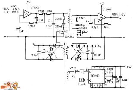
In the figure is the FET wave chopping transformer coupling separating amplifier circuit. The 1~5V DC input signal is impedance-converted by the buffer amplifier A1, and then turned into the AC signal by VT1 chopper, the AC signal is sent to the second stage by transformer T1. After that, it engages in the VT2 ON/OFF control at the second stage and it is rectified synchronously, and then it is changed in to a DC voltage signal which is proportional to the DC voltage signal.
In the circuit, TC4047 composes the multi-resonance oscillator, which generates the 25kHz square wave, and the wave motivates the driver TC426 of VT1 and VT2. (View)
View full Circuit Diagram | Comments | Reading(1421)
Human control electric fan circuit
Published:2011/6/27 22:16:00 Author:chopper | Keyword: Human control, electric fan circuit
View full Circuit Diagram | Comments | Reading(433)
monitor of baby sleep state circuit
Published:2011/6/27 22:17:00 Author:chopper | Keyword: monitor, baby sleep state
View full Circuit Diagram | Comments | Reading(751)
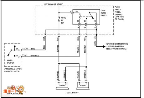
The Volkswagon loudspeaker circuit
Published:2011/6/30 22:55:00 Author:qqtang | Keyword: Volkswagon, loudspeaker
View full Circuit Diagram | Comments | Reading(452)
Vizi saloon car headlight, rear foglight and front foglight circuit
Published:2011/7/1 1:28:00 Author:TaoXi | Keyword: Vizi, saloon car, headlight, rear foglight, front foglight
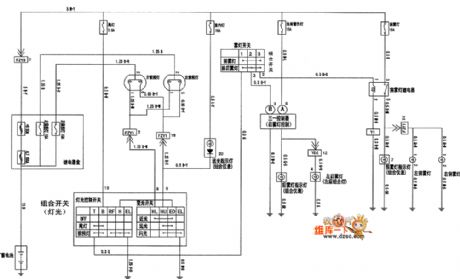
The Vizi saloon car headlight, rear foglight and front foglight circuit is as shown in the figure:
(View)
View full Circuit Diagram | Comments | Reading(410)
| Pages:61/164 At 206162636465666768697071727374757677787980Under 20 |
Circuit Categories
power supply circuit
Amplifier Circuit
Basic Circuit
LED and Light Circuit
Sensor Circuit
Signal Processing
Electrical Equipment Circuit
Control Circuit
Remote Control Circuit
A/D-D/A Converter Circuit
Audio Circuit
Measuring and Test Circuit
Communication Circuit
Computer-Related Circuit
555 Circuit
Automotive Circuit
Repairing Circuit