
Automotive Circuit
Index 71
The frequency counter circuit
Published:2011/6/21 22:09:00 Author:qqtang | Keyword: frequency counter

In the figure is the frequency counter circuit, the upper limit of the frequency testing range is 10kHz or so, the lower limit is several Hz. In the circuit, the 1st bit is fixed as 0, the testing period is 1.2s, LQT-100X is the module on the market. This circuit can be used as the rotating meter, which is installed in the rotating equipment, for example, the spindle of motors is fixed with encoder of 6 pulses/1 round, so that we can read out the rotating speed each minute of the motor, i.e the digital rotating speed meter.
(View)
View full Circuit Diagram | Comments | Reading(1228)
The China 4G22D4 engine control system circuit
Published:2011/6/18 2:36:00 Author:Seven | Keyword: engine control system
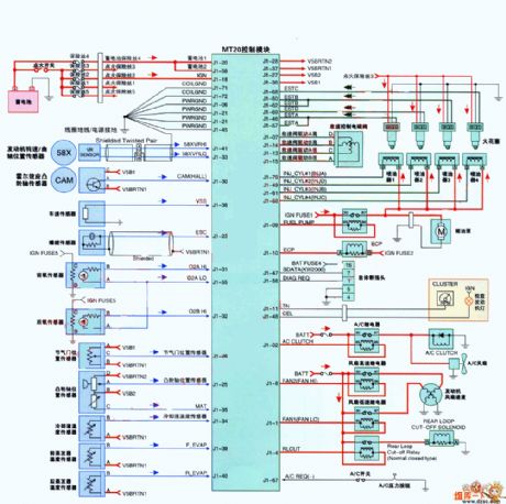
The China 4G22D4 engine control system circuit is shown in the figure.
(View)
View full Circuit Diagram | Comments | Reading(1113)
The general triangular wave generating circuit (741)
Published:2011/6/14 0:24:00 Author:Borg | Keyword: triangular wave

In the figure is the general triangular wave generating circuit (741). In the circuit, the computing amplifiers of A1 and A2 is the positive/passive peak value detector, A3 is the integrator, C1 is the holding capacitor. This circuit can adapt to the temperature of wide range, which has good linearity and amplitude stabilization. The oscillating frequency depends on the time constant R3C2, if Va=8V, the frequency is 1KHz. The ratio between C1 and C2 is 20:1. The computing amplifier is 741. (View)
View full Circuit Diagram | Comments | Reading(528)
The square wave generating circuit composed of LM139
Published:2011/6/14 21:02:00 Author:Borg | Keyword: square wave, circuit
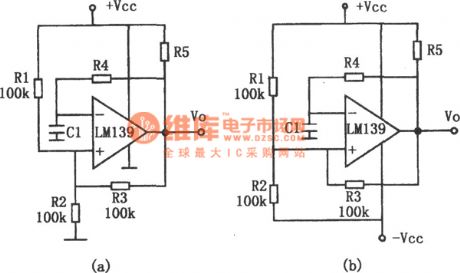
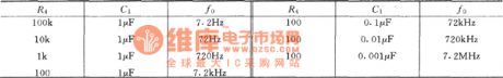
In the figure is the square wave generating circuit. LM139 can be used in oscillating circuits of a few MHZ. This circuit is the square wave generating circuit which consists of few elements. The output frequency of the circuit is decided by the time parameters of R4 and C1, and it is also decided by the lag circuits of R1,R2 and R3. The maximum working frequency is limited by the lagged time of the comparator large signal transmission. Besides, the working frequency is relevant to the loading characteristics. When the circuit is capacitive load, its maximum working frequency is reduced. In the circuit, figure (a) is the single power supply circuit.
(View)
View full Circuit Diagram | Comments | Reading(542)
The sine, square and triangular wave generator(NE566、NE531)
Published:2011/6/14 1:48:00 Author:Borg | Keyword: triangular wave, generator
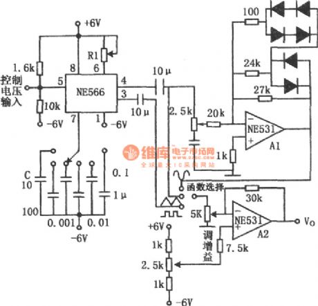
In the figure is sine, square and triangular wave generator. This circuit consists of a voltage control oscillator and two high-speed op-amps, which has a wide frequency range. The oscillator is formed by NE566, whose working frequency range is 0.1Hz~1MHz. Frequency adjustment is done by R1 and C. The triangular and square waves are imposed on the computing amplifier A2 by communication coupling, and they are output by A2. The sine wave converter A1 can switch the triangular wave into the square wave, and the waves are output by A2. The output frequency of the sine wave is 10Hz~1MHz, which is switched by the diode. (View)
View full Circuit Diagram | Comments | Reading(3938)
The M50117F/AP/BP/CP logic frame circuit
Published:2011/6/18 2:50:00 Author:Seven | Keyword: logic frame circuit
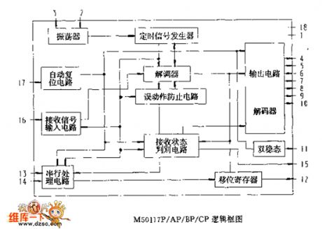
The M50117F/AP/BP/CP logic frame circuit (View)
View full Circuit Diagram | Comments | Reading(409)
The stable square wave and triangular wave generator (118)
Published:2011/6/14 1:18:00 Author:Borg | Keyword: square wave, triangular wave
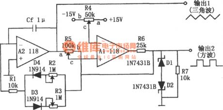
In the figure is the stable square wave and triangular wave generator. The characters of the circuit are that the frequencies of the square wave and triangular wave are nearly the same, the passive and positive amplitudes are symmetric; the positive and passive slopes of the triangular wave are not effected by the amplitude, and the slopes can be adjusted. Besides, the wave shape won't be changed when adjusting the basic LEV. The computing amplifier A2 is the integrator, which is driven by the output square waves. The amplitude of the square wave is fixed at ±5V by the Zener diodes of D1 and D2. (View)
View full Circuit Diagram | Comments | Reading(713)
The sawtooth wave signal generator composed of DAC08EQ
Published:2011/6/14 4:16:00 Author:Borg | Keyword: sawtooth wave, signal generator
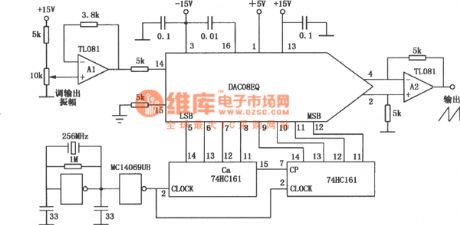
The sawtooth wave signal generator, which consists of DAC08EQ, is simply constructed, and the signal waveform of the generator is highly precise, the generator is used in highly precise signal waveform circuits or instruments. See as the figure. (View)
View full Circuit Diagram | Comments | Reading(526)
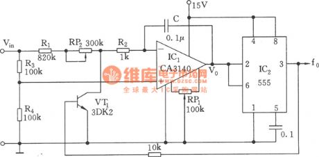
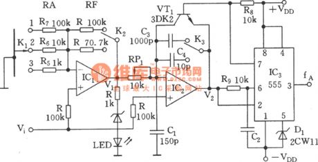
The linear voltage/frequency converter circuit (555)
Published:2011/6/13 21:22:00 Author:Borg | Keyword: voltage/frequency converter


frequency-voltage converting relationship:
(View)
View full Circuit Diagram | Comments | Reading(3016)
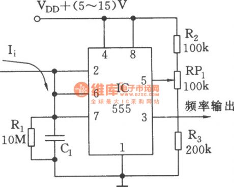
The simple current/frequency converter (555)
Published:2011/6/13 21:19:00 Author:Borg | Keyword: current/frequency converter
View full Circuit Diagram | Comments | Reading(1406)
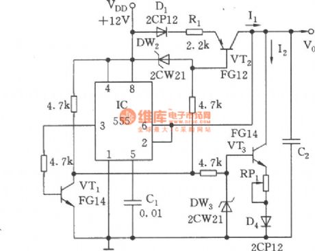
The voltage/frequency converter of low switching parameter (555)
Published:2011/6/13 21:18:00 Author:Borg | Keyword: voltage/frequency converter, switching parameter
View full Circuit Diagram | Comments | Reading(502)
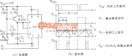
The simple voltage/pulse width converter (555)
Published:2011/6/13 21:15:00 Author:Borg | Keyword: voltage, pulse width, converter
View full Circuit Diagram | Comments | Reading(564)
The adjustable symmetric triangular wave generator circuit (555)
Published:2011/6/13 21:06:00 Author:Borg | Keyword: adjustable, symmetric triangular wave
View full Circuit Diagram | Comments | Reading(812)
The linear sawtooth wave generator circuit of 555
Published:2011/6/13 21:01:00 Author:Borg | Keyword: linear sawtooth wave
View full Circuit Diagram | Comments | Reading(1720)
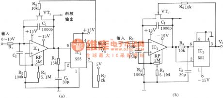
The linear voltage/frequency converter circuit of 555 (2)
Published:2011/6/13 23:32:00 Author:Borg | Keyword: voltage/frequency converter
View full Circuit Diagram | Comments | Reading(391)
The linear voltage/frequency converter circuit of 555 (3)
Published:2011/6/13 23:33:00 Author:Borg | Keyword: voltage/frequency converter
View full Circuit Diagram | Comments | Reading(506)
The linear voltage/frequency converter of 555 (1)
Published:2011/6/13 23:31:00 Author:Borg | Keyword: voltage/frequency converter

View full Circuit Diagram | Comments | Reading(1350)
The sawtooth scanning voltage circuit with good linearity
Published:2011/6/13 20:55:00 Author:Borg | Keyword: sawtooth scanning voltage, linearity
View full Circuit Diagram | Comments | Reading(435)
The MCl45028 logic frame circuit
Published:2011/6/19 3:05:00 Author:Seven | Keyword: logic frame circuit

The logic frame circuit
The MCl45028 logic frame circuit (View)
View full Circuit Diagram | Comments | Reading(432)
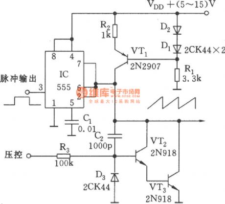
The variable frequency and pulse width waveform generator (555)
Published:2011/6/13 21:13:00 Author:Borg | Keyword: variable frequency, pulse width
View full Circuit Diagram | Comments | Reading(1987)
| Pages:71/164 At 206162636465666768697071727374757677787980Under 20 |
Circuit Categories
power supply circuit
Amplifier Circuit
Basic Circuit
LED and Light Circuit
Sensor Circuit
Signal Processing
Electrical Equipment Circuit
Control Circuit
Remote Control Circuit
A/D-D/A Converter Circuit
Audio Circuit
Measuring and Test Circuit
Communication Circuit
Computer-Related Circuit
555 Circuit
Automotive Circuit
Repairing Circuit