
Automotive Circuit
Index 60
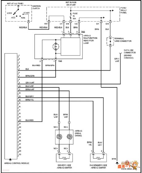
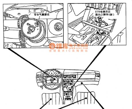
Volkswagen airbag circuit
Published:2011/7/5 20:02:00 Author:Christina | Keyword: Volkswagen, airbag circuit
View full Circuit Diagram | Comments | Reading(1767)
ChangFeng LieBao SUV combination meter circuit
Published:2011/7/5 20:33:00 Author:Christina | Keyword: ChangFeng, LieBao, SUV, combination meter
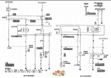
The ChangFeng LieBao SUV combination meter circuit is as shown in the figure:
(View)
View full Circuit Diagram | Comments | Reading(417)
BMW8 series anti-theft device location circuit
Published:2011/7/5 19:10:00 Author:Christina | Keyword: BMW8 series, anti-theft device, location circuit
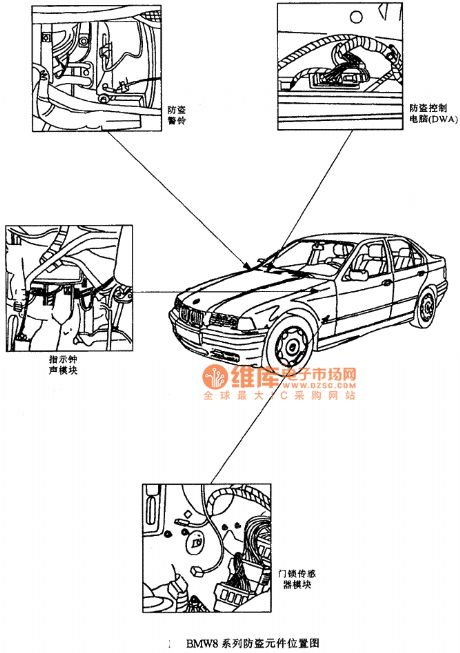
BMW8 series anti-theft device location circuit (View)
View full Circuit Diagram | Comments | Reading(418)
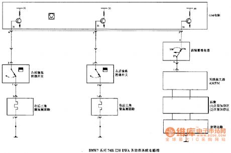
BMW7 series 740i E38DWA IV anti-theft system circuit (4)
Published:2011/7/5 19:12:00 Author:Christina | Keyword: BMW7 series, 740i, anti-theft system
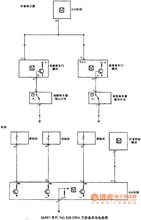
BMW7 series 740i E38DWA IV anti-theft system circuit (4)
(View)
View full Circuit Diagram | Comments | Reading(363)
BMW7 series 740i E38DWA IV anti-theft system circuit (3)
Published:2011/7/5 19:17:00 Author:Christina | Keyword: BMW7 series, 740i, anti-theft system
BMW7 series 740i E38DWA IV anti-theft system circuit (3)
(View)
View full Circuit Diagram | Comments | Reading(407)
Volkswagen electric door lock circuit
Published:2011/7/5 20:01:00 Author:Christina | Keyword: Volkswagen, electric door, lock circuit

View full Circuit Diagram | Comments | Reading(740)
Volkswagen start-up circuit
Published:2011/7/5 20:01:00 Author:Christina | Keyword: Volkswagen, start-up circuit

View full Circuit Diagram | Comments | Reading(437)
Benz fault diagnosis process circuit
Published:2011/7/4 21:16:00 Author:Christina | Keyword: Benz, fault diagnosis, process circuit
Benz fault diagnosis process circuit
(View)
View full Circuit Diagram | Comments | Reading(419)
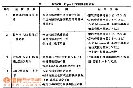
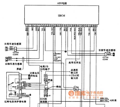
BENZ BOSCH-35pin ABS system circuit
Published:2011/7/4 21:15:00 Author:Christina | Keyword: BENZ, BOSCH-35pin, ABS, system circuit

BENZ BOSCH-35pin ABS system circuit
(View)
View full Circuit Diagram | Comments | Reading(610)
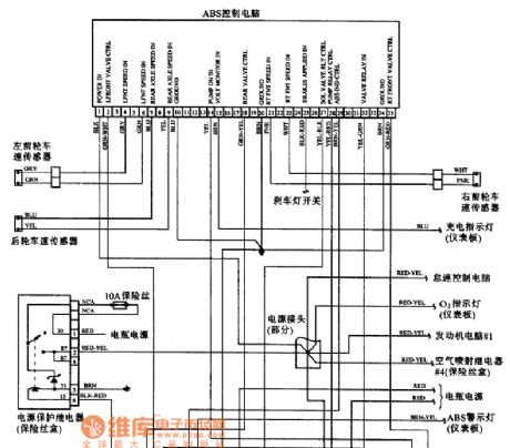
BENZ 300 and 260 series ABS system circuit
Published:2011/7/4 21:14:00 Author:Christina | Keyword: BENZ, 300, 260 series, ABS, system circuit
BENZ 300 and 260 series ABS system circuit
(View)
View full Circuit Diagram | Comments | Reading(415)
the circuit of the animal baby announcer (2)
Published:2011/6/27 23:36:00 Author:Ariel Wang | Keyword: animal baby , announcer
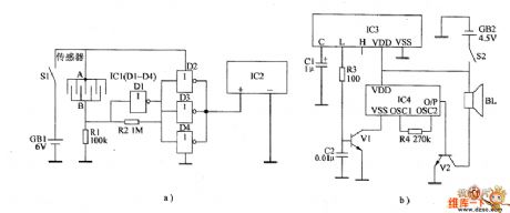
In normal times,the resistence between the sensor's electrode A and B is large.The input end of not gate D1 outputs low level.The output end outputs high level.The output ends of not gate D2~D4 output low level.IC2 stops working.The wireless receiving alarm circiut can't receive wireless alarm signal.The loudspeaker BL can't give a sound.When animals have babies,the resistence between the sensor's electrode A and B is small.The not gate outputs low level.The not gate D2~D4 output high level.IC2 is conducted to work.It emits wireless alarm signal to the sky.When IC3 recieves the wireless signal from IC2,the L end outputs high level,V1 is saturated to conduct.IC4 is conducted to work.The O/P end outputs acoustics signal.It is amplified by V2.The driver BL gives out alarm sound. (View)
View full Circuit Diagram | Comments | Reading(453)
the circuit of the chickling hatching announcer(2)
Published:2011/6/28 6:59:00 Author:Ariel Wang | Keyword: chickling hatching, announcer
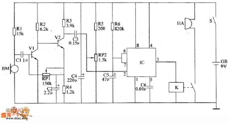
BM is as the audio sensor .It used to detect if there is any chickling hatching from the eggs.When the sound signal is not detected by BM.The mono-stable delay circuit is at the steady state.The pin-3 of IC outputs low level.K is released.The buzzer HA doesn't give a sound.When there is any chickling hatching from the eggs in the incubator.BM will convert the detected sound of the chickling into the electric signal.The signal is amplified by V1 and V2.Then it generates the triggering signal.The mono-stable trigger circuit is triggered to turn over.It turns to transient stability from steady state.The pin-3 of IC outputs high level from low level.K is conducted to pull in.The normally open contacts are connected.The buzzer HA gives out alarm sound.It informs the worker there are chicklings hatching from the eggs. (View)
View full Circuit Diagram | Comments | Reading(462)
the circuit of the automatic anti-frosting controller for crops(1)
Published:2011/6/29 0:03:00 Author:Ariel Wang | Keyword: automatic, anti-frosting , controller, crops
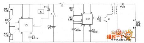
When the atmospheric temperature is higher than +1℃,the pin-2 of IC1 outputs the voltage lower than 3V.K is released.The high voltage ignition circuit stops working.When the temperature goes down an the condition of frost is formed,the resistence of RT is increased.The voltage of IC1's pin-6 is higher than 6V.The pin-3 outputs high level.K is conducted to pull in.The normally open contacts are connected.The high voltage ignition is conducted to work.It generates near 10000V DC voltage between electrodes of A and B.It lights the gunpowder and gasoline.The smoking material is infamed.
(View)
View full Circuit Diagram | Comments | Reading(455)
the alarm circuit of water break in the spray pipe for seeding-machine(4)
Published:2011/6/29 7:13:00 Author:Ariel Wang | Keyword: alarm , water break , spray pipe , seeding-machine
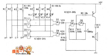
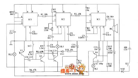
When the spray pipe is blocked,the output end of the not gate outputs high level.The output end becomes low level.The LED of the circuit is lighted.It indicates how many the blocked spray pipes are.At the same time,the audio oscillatory circuit works.BL gives out alarm sound.For example,the spray pipes in circuit A are blocked.Then there's no water in sprayer spraying out.The not gate D1 outputs low level.VL1 is lighted.The NAND gate D5 outputs high level.VD1 is conducted.The audio oscillator works.After the audio oscillatory signal is amplified by V,the driver BL gives out alarm sound. (View)
View full Circuit Diagram | Comments | Reading(477)
the alarm circuit of water break in the spray pipe for seeding-machine(3)
Published:2011/6/30 7:42:00 Author:Ariel Wang | Keyword: alarm , water break , spray pipe , seeding-machine
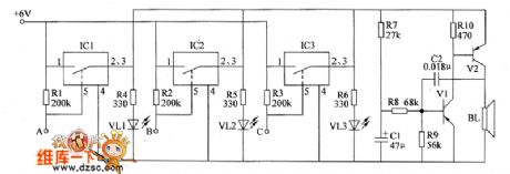
The water break detected circuit consists of switch integrated circuit IC1~IC3 and the resistor RI~R3。The ends of A~C are connected with water spray pipes of three circuits.When any water spray pipe is blocked,the pin-5 of the electronic switch integrated circuit becomes high level.The electronic switch inside is connected and conducted.The LED is lighted.It indicates how many the blocked water sprays are.At the same time,the audio oscillator circuit works.BL gives out alarm sound.For example,the water spray pipe in circuit A is blocked,there is no water spraying out from the sprayer.The electronic switch inside IC1 is conducted.VL1 is lighted.V1 and V2 are conducted to work.BL gives out the alarm sound.
(View)
View full Circuit Diagram | Comments | Reading(439)
the alarm circuit of the blocked seed channel in seeding-machine (2)
Published:2011/7/1 17:41:00 Author:Ariel Wang | Keyword: alarm , blocked , seed channel , seeding-machine
The photoelectric sensor consists of HL3 and V1.It used to detect if there are seeds in the seed channel.When seeding,the seed passes through the optical path of the photoelectric sensor constantly.It breaks the optical path between HL3 and V1.The internal resistance is large.At this time,V2 is saturated to conduct.V3 is stopped.HL1 is not lighted.The pin-3 of IC1 outputs low level.The 1Hz multivibrator and 1kHz multivibrator are not working.B1 doesn't give a sound.When the seed channel is blocked or there are no seeds,the light of HL3 shines on V1.V1 is with the low resistivity.V2 is stopped.V3 is conducted.HL1 is lighted.
(View)
View full Circuit Diagram | Comments | Reading(543)
BENZ 300SDL, 420, 560DEL and 560SEC ABS system circuits
Published:2011/7/4 3:36:00 Author:Christina | Keyword: BENZ, ABS system
BENZ 300SDL, 420, 560DEL and 560SEC ABS system circuits
(View)
View full Circuit Diagram | Comments | Reading(436)
Vehicle circuit with the 8-pin diagnosis connector
Published:2011/7/4 1:57:00 Author:Christina | Keyword: Vehicle circuit, 8-pin, diagnosis connector
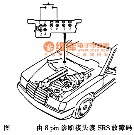
Vehicle circuit with the 8-pin diagnosis connector
(View)
View full Circuit Diagram | Comments | Reading(443)
Benz SRS composition and installation location circuit
Published:2011/7/4 2:01:00 Author:Christina | Keyword: Benz, SRS, composition, installation, location circuit
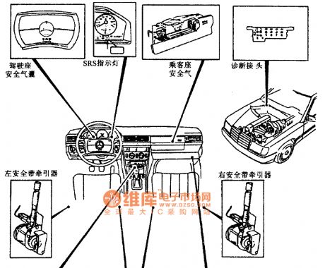
Benz SRS composition and installation location circuit
(View)
View full Circuit Diagram | Comments | Reading(484)
Benz W140 model SRS composition and installation location circuit
Published:2011/7/4 1:59:00 Author:Christina | Keyword: Benz, SRS, composition, installation location
Benz W140 model SRS composition and installation location circuit
(View)
View full Circuit Diagram | Comments | Reading(671)
| Pages:60/164 At 204142434445464748495051525354555657585960Under 20 |
Circuit Categories
power supply circuit
Amplifier Circuit
Basic Circuit
LED and Light Circuit
Sensor Circuit
Signal Processing
Electrical Equipment Circuit
Control Circuit
Remote Control Circuit
A/D-D/A Converter Circuit
Audio Circuit
Measuring and Test Circuit
Communication Circuit
Computer-Related Circuit
555 Circuit
Automotive Circuit
Repairing Circuit