
Automotive Circuit
Index 43
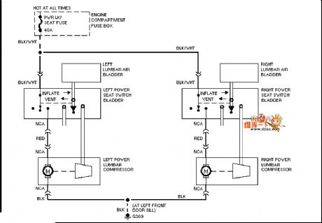
Mazda 95TAURUS electric seat waist circuit diagram
Published:2011/7/18 5:38:00 Author:nelly | Keyword: Mazda, electric seat, waist
View full Circuit Diagram | Comments | Reading(453)
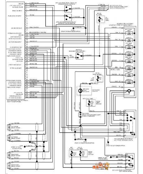
Mazda 94TAURUS(3.0L)ABS circuit diagram
Published:2011/7/18 5:40:00 Author:nelly | Keyword: Mazda, ABS
View full Circuit Diagram | Comments | Reading(384)
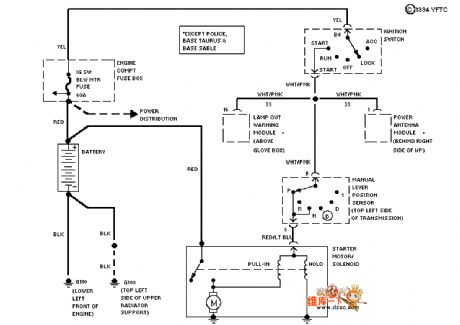
Mazda 94TAURUS(3.0L)starting circuit diagram
Published:2011/7/18 5:40:00 Author:nelly | Keyword: Mazda, starting
View full Circuit Diagram | Comments | Reading(422)
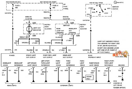
Mazda 94TAURUS(3.8L)car light monitor circuit diagram
Published:2011/7/18 5:40:00 Author:nelly | Keyword: Mazda, car light monitor
View full Circuit Diagram | Comments | Reading(533)
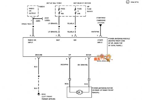
Mazda 94TAURUS electrical antenna circuit diagram
Published:2011/7/18 5:40:00 Author:nelly | Keyword: Mazda, electrical antenna
View full Circuit Diagram | Comments | Reading(446)
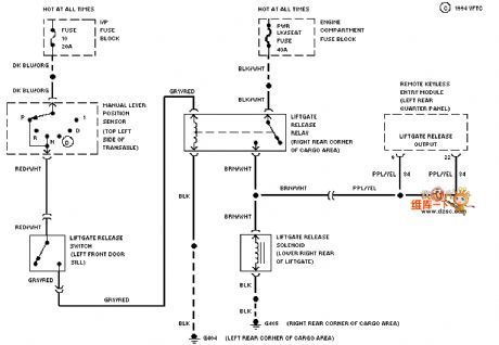
Mazda 94TAURUS back door circuit diagram
Published:2011/7/18 5:40:00 Author:nelly | Keyword: Mazda, back door
View full Circuit Diagram | Comments | Reading(398)
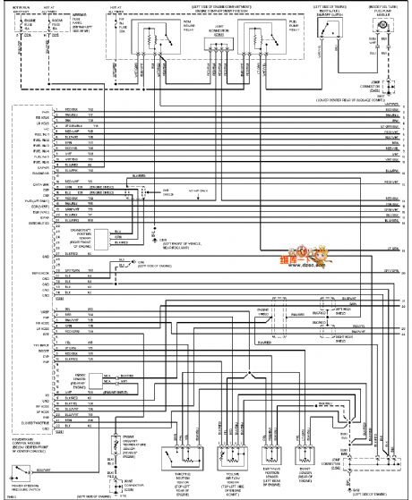
Mazda 96PROBE(2.5L) motor performance circuit diagram
Published:2011/7/18 5:40:00 Author:nelly | Keyword: Mazda, motor performance
View full Circuit Diagram | Comments | Reading(412)
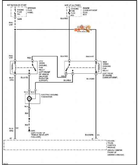
Mazda 96PROBE fan in air conditioner circuit diagram
Published:2011/7/18 5:41:00 Author:nelly | Keyword: Mazda, fan, air conditioner
View full Circuit Diagram | Comments | Reading(656)
Mazda 96PROBE horn circuit diagram
Published:2011/7/18 5:41:00 Author:nelly | Keyword: Mazda, horn
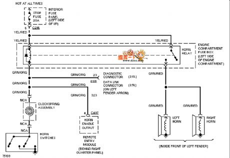
View full Circuit Diagram | Comments | Reading(443)
The 3.0L engine oil level sensor circuit of Shanghai GM Buick-MPV (GL8)
Published:2011/7/20 0:01:00 Author:Borg | Keyword: oil level sensor, Buick-MPV
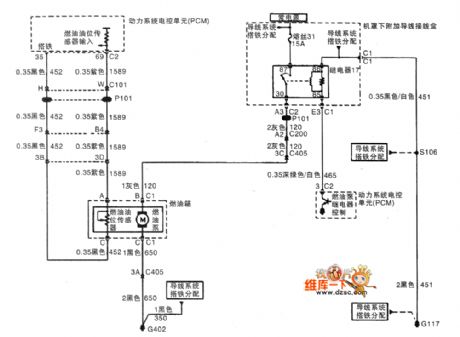
The 3.0L engine oil level sensor circuit of Shanghai GM Buick-MPV (GL8)
(View)
View full Circuit Diagram | Comments | Reading(1726)
The cruise control system of Buick-Regal
Published:2011/7/20 0:01:00 Author:Borg | Keyword: cruise control system, air flow
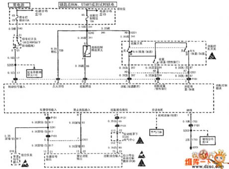
Figure 1: The cruise control system of Shanghai GM Buick-Regal (View)
View full Circuit Diagram | Comments | Reading(531)
The wiper/washer system of Buick-Regal
Published:2011/7/20 Author:Borg | Keyword: wiper/washer system, air flow
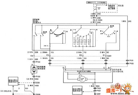
Figure 1: The wiper/washer system of Shanghai GM Buick-Regal (View)
View full Circuit Diagram | Comments | Reading(433)
The backup lamp and instrument circuit of Santana 2000(figure 1 and 2)
Published:2011/7/15 19:17:00 Author:Borg | Keyword: backup lamp, instrument circuit

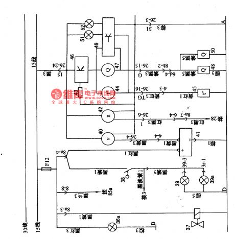
Figure1. The backup lamp and instrument circuit of Santana 2000 (gasoline injection engine)36a-light switch lighting lamp; 37-electromagnet valve; 38-backup lamp switch; 39-backup(left); 40-car speed odometer; 41-speedometer sensor; 42-engine tachometer; 34-resistor divider; 44-thermometer; 45-thermometer sensor; 46-water temperature and fuel signal amplifier; 50-fuel meter sensor(gasoline injection engine); 51-coolant alarm lamp; 52-fuel alarm lamp
(View)
View full Circuit Diagram | Comments | Reading(414)
The headlight and fog light circuit of Nanjing Iveco light car
Published:2011/7/15 19:16:00 Author:Borg | Keyword: headlight, light car
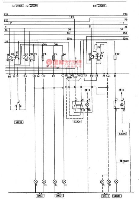
The lighting system(see as figure 3) is controlled by the external lamp switch 52307, the switch power comes from two sources, the current of the width lamp, tail lamp and license lamp is connected with No.30 wire (battery positive pole), as long as the switch is at the 1 or 2 gear, it is passable, and the current of the head light relay coil is led to cylinder 4 of switch 52307 from the igniting switch, if the igniting switch is cut off, the current can not be connected with the headlight. If the external is at 2 gear, one of the relay 25009 of high beam and the relay 25008 is closed.
(View)
View full Circuit Diagram | Comments | Reading(537)
The air-conditioning circuit of Nanjing Iveco light car
Published:2011/7/15 19:14:00 Author:Borg | Keyword: air-conditioning circuit, light car
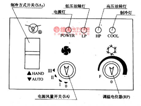
(18) The air-conditioning circuit of Nanjing Iveco light carThe air-conditioning system of Nanjing Iveco light car is in a non-independent structure, which is driven by the engine crankshaft belt with the help of compressor and electromagnetic clutch, and whether electromagnetic clutch is separated or connected is decided by the temperature control switch(manual or auto or their combination), the cooling part consists of the compressor, condenser, liquid storing tank, swelling valve, evaporator, electric control system and tube, etc. The coolant is R-12 (freon), and it refrigerates in the vapor compressing method.
(View)
View full Circuit Diagram | Comments | Reading(448)
The Toyota starting motor circuit
Published:2011/7/13 23:14:00 Author:Borg | Keyword: Toyota, starting motor
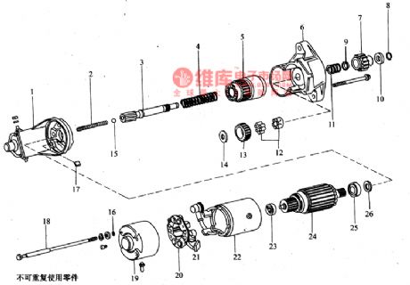
3.starting motor The Toyota-Coster bus diesel engine is installed with an electric starting motor which is electromagnetic inter meshing decelerating type, the voltage systems are 12V and 24V, the powers are 2.5kW and 4.5kW. The parameters of the starter are shown in figure 4.
(View)
View full Circuit Diagram | Comments | Reading(452)
The car electronic fuel-saving device (2)
Published:2011/7/20 1:10:00 Author:TaoXi | Keyword: car, electronic, fuel-saving device
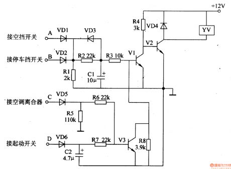
The principle of the circuit
The car electronic fuel-saving device is composed of the diodes VD1-VD6, the resistors R1-R8, the capacitors C1 and C2, the transistors V1-V3 and the electromagnetic valve YV, the circuit is as shown in figure 7-140.
Components selection
R1-R8 are the 1/4W metal film resistors or the carbon film resistors.C1 and C2 are the 16V aluminum electrolytic capacitor.VD1-VD6 are the 1N4007 silicon rectifier diode.V1 and V3 are the S8050 NPN transistors; V2 uses the DDO3 silicon NPN transistor.YU uses the 12V DC electromagnetic valve.
(View)
View full Circuit Diagram | Comments | Reading(1501)
The car electronic fuel-saving device (1)
Published:2011/7/20 1:05:00 Author:TaoXi | Keyword: car, electronic, fuel-saving device
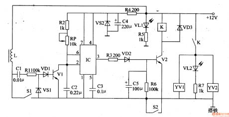
The principle of the circuit
The car electronic fuel-saving device is composed of the transistors Vl and V2, the integrated circuit IC, the relay K, the electromagnetic valves YVl and YV2 and the external components, the circuit is as shown in figure 7-139.
Components selection
The Rl-R3 and R5-R7 are the 1/4W carbon film resistors; the R4 is the lW carbon film resistor.RP is the membrane type variable resistor.Cl-C3 are the monolithic capacitor or the polyester capacitor; the C4 and C5 are the 16V aluminum electrolytic capacitor.VDl-VD3 are the 1N4001 or 1N4007 silicon rectifier diode.The VSl are the 1/4W, 1.8V voltage stabilization diode such as the 1N4614, 2CW5O; VS2 is the 1.5W、6.1V voltage stabilization diode such as the 1N5920.
(View)
View full Circuit Diagram | Comments | Reading(2091)
Motorcycle electronic ignition (2)
Published:2011/7/20 2:33:00 Author:TaoXi | Keyword: Motorcycle, electronic, ignition
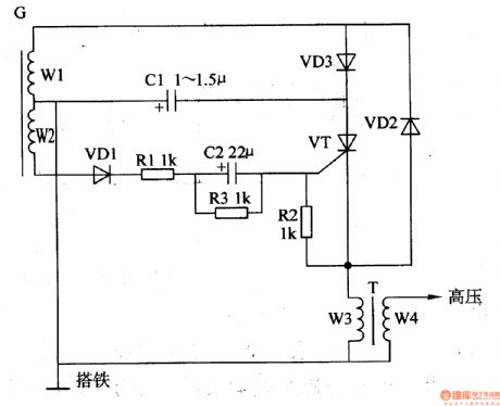
The principle of the circuit
The motorcycle electronic ignition circuit is composed of the resistors R1-R3, the capacitors C1 and C2, the diodes VD1-VD3, the thyristor VT and the magnetor charging coil W1, the control coil W2, the ignition coil T, the circuit is as shown in figure 7-138. The output AC of the magnetor winding W1 is half-wave rectified by VD3 to charge the C1.
Components selection
The R1-R3 use the 1/4W metal film resistor.The C1 uses the 400V CBB capacitor or the polyester capacitor; C2 uses the 5OV aluminum electrolytic capacitor.The VD1-VD3 use the 1N4007 silicon rectifier diode.The VT uses the 2P4M(2A, 400V) thyristor.
(View)
View full Circuit Diagram | Comments | Reading(2990)
Automotive speed limiter
Published:2011/7/20 19:21:00 Author:Lucas | Keyword: Automotive , speed limiter
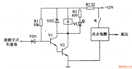
The automotive electronic speed limiter circuit consists of transistors Vl, V2, relay K, resistors Rl-R3, diodes VDl, VD2, and light-emitting diode VL, and the circuit is shown in Figure 7-172. Rl and R2 select 1/4W metal film resistors; R3 selects the lW metal film resistor. VDl and VD2 use 1N4148 silicon switch diode or lN4007 rectifier diode. Vl uses S9013 silicon NPN transistor; V2 uses the S8050 silicon NPN transistor. K selects the 4088 or 4098 12V DC relay.
(View)
View full Circuit Diagram | Comments | Reading(1406)
| Pages:43/164 At 204142434445464748495051525354555657585960Under 20 |
Circuit Categories
power supply circuit
Amplifier Circuit
Basic Circuit
LED and Light Circuit
Sensor Circuit
Signal Processing
Electrical Equipment Circuit
Control Circuit
Remote Control Circuit
A/D-D/A Converter Circuit
Audio Circuit
Measuring and Test Circuit
Communication Circuit
Computer-Related Circuit
555 Circuit
Automotive Circuit
Repairing Circuit