Automotive Circuit
Motorcycle electronic ignition (2)
Published:2011/7/20 2:33:00 Author:TaoXi | Keyword: Motorcycle, electronic, ignition | From:SeekIC

The principle of the circuit
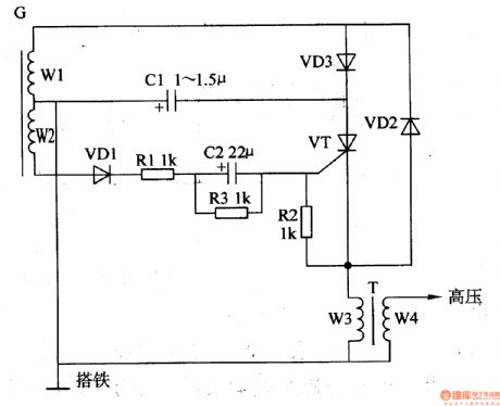
The motorcycle electronic ignition circuit is composed of the resistors R1-R3, the capacitors C1 and C2, the diodes VD1-VD3, the thyristor VT and the magnetor charging coil W1, the control coil W2, the ignition coil T, the circuit is as shown in figure 7-138. The output AC of the magnetor winding W1 is half-wave rectified by VD3 to charge the C1.
Components selection
The R1-R3 use the 1/4W metal film resistor.The C1 uses the 400V CBB capacitor or the polyester capacitor; C2 uses the 5OV aluminum electrolytic capacitor.The VD1-VD3 use the 1N4007 silicon rectifier diode.The VT uses the 2P4M(2A, 400V) thyristor.
Reprinted Url Of This Article:
http://www.seekic.com/circuit_diagram/Automotive_Circuit/Motorcycle_electronic_ignition_2.html
Print this Page | Comments | Reading(3)

Article Categories
power supply circuit
Amplifier Circuit
Basic Circuit
LED and Light Circuit
Sensor Circuit
Signal Processing
Electrical Equipment Circuit
Control Circuit
Remote Control Circuit
A/D-D/A Converter Circuit
Audio Circuit
Measuring and Test Circuit
Communication Circuit
Computer-Related Circuit
555 Circuit
Automotive Circuit
Repairing Circuit
Code: