
Automotive Circuit
Index 44
Motorcycle electronic ignition (1)
Published:2011/7/20 1:48:00 Author:TaoXi | Keyword: Motorcycle, electronic, ignition

The principle of the circuit
The motorcycle electronic ignition is composed of the time base integrated circuit IC, the switching tube V, the voltage stabilization diode VS, the diode VD and the external components, the circuit is as shown in figure 7-137.
The monostable circuit is composed of the IC, the resistors R1 and R2, the capacitor C1-C3.
The +l2V voltage is reduced and limited by the diode VD and R3, then it is stabilized by VS to be the +5.lV (Vcc) voltage that can be used as the operating voltage of IC.
Components selection
R1, R2 and R4 are the 1/4W carbon film resistors; R3 is the 1W carbon film resistors;C1 is the high-frequency ceramic capacitor; C2 and C3 use the polyester capacitor or monolithic capacitor.
(View)
View full Circuit Diagram | Comments | Reading(5576)
Time-scale sawtooth wave generation circuit
Published:2011/7/11 23:32:00 Author:chopper | Keyword: Time-scale, sawtooth wave, generation circuit

View full Circuit Diagram | Comments | Reading(456)
rice processing machine controller
Published:2011/7/19 23:42:00 Author:chopper | Keyword: rice, processing machine , controller
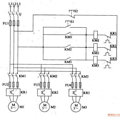
This example describes the rice processing machine controller, which uses the control button to coordinate with the AC contactor,thermal relay and other auto-electrical devices,and it can enable the automatic protection control of electric motor. The principle of circuit This rice processing machine controller circuit is formed by knife switch Q,fuses FU1-FU4, start button S1,stop button S2, AC contactors KM1-KM3 and thermal relays KR1-KR3,which is shown in Figure 4-132. (View)
View full Circuit Diagram | Comments | Reading(447)
Circuit of a Low-pass Filter Composed of Same Parameters with 24 dB Every Octave
Published:2011/7/15 0:58:00 Author:Joyce | Keyword: Low-pass, Filter, Same Parameters, 24 dB, Every Octave
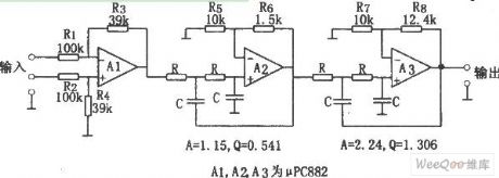
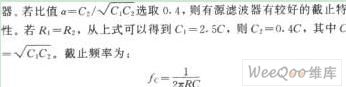
As shown in the figure is the circuit of a low-pass filter composed of same parameters with 24 dB every octave. This circuit is a low-pass filters with 24 dB every octave, which is formed of filtering components of same parameters. In order to get the needed Q value, open-loop op-amp is set to be greater than 1,and at this time the input op-amp becomes 1/2.57 attenuator. The characteristics of the circuit is that when it constitutes multilevel filters, using resistance R of cut-off frequency fc and capacitance C would get the same constant. The parameters of the components in the circuit can be calculated according to the formula fc = 1 / (2 π RC) .The value of resistance ranges from several k Ω to a few hundred k Ω, and the value of capacitance is above several hundred pF.
(View)
View full Circuit Diagram | Comments | Reading(796)
Active Lowpass Filter Circuit with Attenuation of -18dB Every Octave
Published:2011/7/20 3:08:00 Author:Joyce | Keyword: Active , Lowpass, Filter Attenuation , -18dB, Every Octave

As shown in the figure is an active low pass filter circuit with attenuation of -18dB every octave. The circuit is composed of a passive filter with attenuation of -6 dB every octave and an active filter with attenuation of -12 dB every octave. The whole circuit shows a low pass filter with attenuation of -18 every octave. R1 and C3 form the passive filter, and R2, R3, C1, C2 and operational amplifier constitute the active filter.
(View)
View full Circuit Diagram | Comments | Reading(1099)
Power Line Carrier Remote Alarm Circuit
Published:2011/7/20 3:09:00 Author:Joyce | Keyword: Power Line , Carrier, Remote Alarm
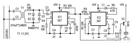
The alarm introduced here does not need circumscribed circuit, but an electric power circuit to send warning signs. Alarm points can be set in many places to conduct sound and light alarm warning for an emergency. It can be used extensively.
Working principle:
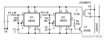
This alarm is composed of sending and receiving signals .The principle of the reflection circuit is as shown in figure 1. It shows two oscillating circuits with different frequency formed by the two 555 time base circuits. When two ends of CK form a short circuit (short circuit alarm probe signal), the first piece (IC1) 555 constitutes a low frequency oscillation circuit, and frequency F1 is mainly decided by C1, R2, and output frequency of feet 3 is the low frequency signal of F1.When feet 3 of IC1 outputs high levels , the second piece IC2 (555) constitutes a high frequency oscillation circuit, and the oscillation frequency is mainly decided by C3, R4.
Components selection and circuit adjustment:
 (View)
View full Circuit Diagram | Comments | Reading(4584)
ZhongHua saloon car ABS circuit 2
Published:2011/7/11 2:48:00 Author:TaoXi | Keyword: ZhongHua, saloon car, ABS
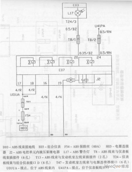
ZhongHua saloon car ABS circuit
D10-ABS wiring harness ground wireE03-Combination instrument F54-ABS fuse (60A)H03-power supply connectorJ2-ABS electric control unit hydraulic pump relay L17-ABS alarm lightT8-ABS wiring harness and dashboard wiring harness plug connector (6 holes)T13-ABS wiring harness and engine room left wiring harness plug connector (2 holes)T24-Dashboard wiring harness and combination instrument interface D (8 holes)T47-Engine room left wiring harness and power supply connector interface (6 holes)U01UA-Connection point, in the ABS wiring harnessU41PA-Connection point, in the dashboard wiring harness (View)
View full Circuit Diagram | Comments | Reading(535)
GuangZhou HONDA Fit saloon car engine circuit 9
Published:2011/7/11 2:36:00 Author:TaoXi | Keyword: GuangZhou, HONDA, Fit, saloon car, engine circuit
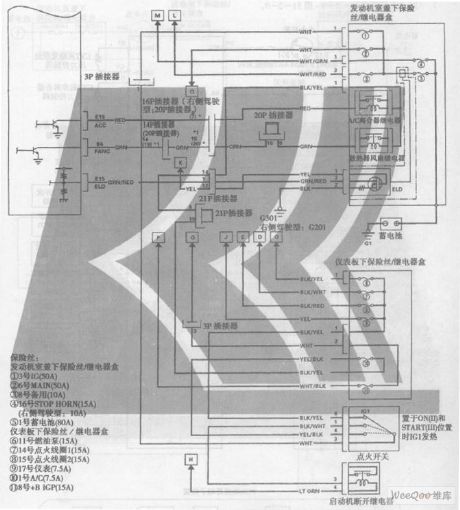
GuangZhou HONDA Fit saloon car engine circuit
Fuse:
Engine room under-cover fuse/relay box
1. Number 3 IG(50A)
2. Number 6 MAIN(50A)
3. Number 8 spare(10A)
4. Number 16 STOP HORN(15A) (Right side of the cab: 10A)
5. Number 1 storage battery(80A)
The fuse/relay box below the instrument panel
6. Number 11 fuel pump(15A)
7. Number 14 ignition coil 1 (15A)
8. Number 15 ignition coil 2 (15A)
9. Number 17 meter(7.5A)
10. Number 1 A/C(7.5A)
11. Number 8 +B IGP(15A) (View)
View full Circuit Diagram | Comments | Reading(791)
The Spread Spectrum Rolling code Wireless Tracking Alarm Components KB318/KB318R
Published:2011/7/18 21:46:00 Author:TaoXi | Keyword: Spread Spectrum, Rolling code, Wireless Tracking, Alarm Components
The spread spectrum rolling code wireless tracking alarm component can be used in the situations that need the long distance wireless BP machine type feedback alarm such as the cars, motorcycles and other, it uses the advanced technology and devices, so it has the perfect functions and is better than other similar products. The spread spectrum rolling code wireless tracking alarm component is composed of a wireless transmitter KB318T (or KB923T), and a key buckle type micro receiving alarm KB318R (or KB923R). The remote control transmitter principle figure is as shown:
(View)
View full Circuit Diagram | Comments | Reading(296)
Benz fault code reading and clearing circuit diagram
Published:2011/7/20 20:18:00 Author:Ecco | Keyword: Benz , fault code , reading , clearing

In the figure, the LED light is connected across thesecond and 31th hole ofthe 38th diagnostic connector. (View)
View full Circuit Diagram | Comments | Reading(449)
Car voltage supervisory circuit
Published:2011/5/12 22:37:00 Author:Nicole | Keyword: car voltage

This cirucit is suitable for monitoring whether the 12V car power voltage is normal. If the power voltage is between 12~14.5V, then it is normal; if the voltage is lower than 12V or higher than 14.5V, the indicator light will shine respectively.
A1, A2 are indicator light comparators,they areused to adjust potentiometers W1, W2. When the car power supply is higher than 14.5V, B light turns on; if the power voltage is lower than 12V, A light turns on; if it is normal, the two lights are all off. (View)
View full Circuit Diagram | Comments | Reading(539)
Motorcycle ignition circuit
Published:2011/5/12 4:02:00 Author:Nicole | Keyword: motorcycle, ignition

LZ4213 function foot: P1-VCC; P2-input+; P3-VSS; P4-VSS; P5-VSS; P6-VSS; P7-input-; P8-bias; P9-bias; P10-output; P11-adjustment1; P12-adjustment2; P13-reference; P14-adjustment3
The working principle of circuit:When the engine is turning, phase pulsepasses IC1-P2, P10, output a positive pulse in P10 terminal, it changes with rotational speed, SCR1 is triggered and then it is turned on, at this time, capacitance is discharged to L2 primary coilby SCR1 immediately, and inducing high voltage EMF in L2 secondary winding, thenitlights afirethrough spark plug. IC1-P13 external connection of integral voltage waveform set by C7, the integral voltage waveform on IC1-P12 terminal is from internal into angle voltage comparator, the switch is controlled by the angle, it produces a phase which advances the falling edge of PC pulse, it achieves automatic adjustment ignition advance angle by tracking motor rotational speed. (View)
View full Circuit Diagram | Comments | Reading(1214)
Outlander Jeep engine ingition system circuit diagram
Published:2011/5/12 22:22:00 Author:Nicole | Keyword: Outlander Jeep, engine, ingition system
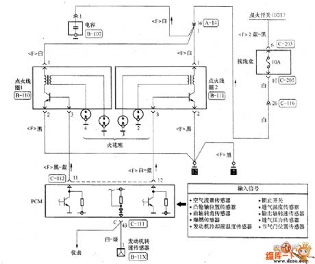
The engine ingition system circuit diagram is as shown, this engine has two ignition coils, the ignition coil 1 isused by 1 vat and 4 vat, the ignition coil 2 isused by 2 vat and 3 vat, because the 1 vat and 4 vat do not work at the same time, so the ignition coil 1 does not work. The ignition switch is cut off, the porous plug of two ignition coils are pulled down, then the ignition switch is turned on, a test lamp is adopted to measure(when it detects the power supply circuit, it should use test lamp to detect).
(View)
View full Circuit Diagram | Comments | Reading(618)
Honda Accord 2.3L car electric seat circuit principle diagram
Published:2011/5/12 22:20:00 Author:Nicole | Keyword: Honda Accord, 2.3L car, electric seat
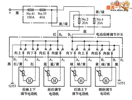
The anode wire(black) which comes from power supply pass the o. 41 fuse (100A) and the No. 55 fuse (40A) of the motor fuse/relay box, then it passes two parallel separate circuit and the No. 2 fuse (20A) and No. 4 fuse (20A) of the fuse/relay box under co-pilot side instrument panel, it came into electric seat regulation switch. When the switch is in one of adjustment state, the current flows to the relevant adjustment motor by switch contact, it drives motor to work, then it achieve adjustment, at last, the loop is completed by B5, B1 ground. (View)
View full Circuit Diagram | Comments | Reading(1404)
Shanghai GM Regal 2.0L throttle position sensor connector terminal and connecting circuit diagram
Published:2011/5/12 22:15:00 Author:Nicole | Keyword: Shanghai GM Regal, throttle, position sensor, connector terminal
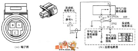
When the throttle is closed, the output voltage is lower, when the throttles are all open, the output voltage is higher than 4.0V. The electronic control unit calculates the fuel supply quantity, ignition timing, idle speed, exhaust gas recirculation, fuel evaporation emission control and air conditioner disconnection control according to throttle opening signal. The sensor connector terminal and connecting circuit is shown as below.
①Checking power voltage. The ignition switch is opened, the voltage between measuring terminal A and ground is 5V. ②Checking sensor's turning situation. The sensor terminal B and ground should be turned on.
(View)
View full Circuit Diagram | Comments | Reading(602)
Shanghai GM Regal 2.0L oxygen sensor connector terminal and connecting circuit diagram
Published:2011/5/12 22:14:00 Author:Nicole | Keyword: Shanghai GM Regal, 2.0L oxygen sensor, connector terminal
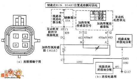
The oxygen sensor is fixed in exhaust manifold, the sensor's signal voltage inputs ECM, according to the input singal voltage, ECM can identify the oxygen content of exhaust pipe. When the mixture is thin, then the oxygen content is high, the sensor outputs about 0.1V low level; when the mixture is thick, the oxygen content is low, the sensor outputs about 0.9V high level. The oxygen sensor singal voltage changes between 0.1~0.9V, ECM will modify the fuel injection quantity according to the oxygen sensor singal.
(View)
View full Circuit Diagram | Comments | Reading(956)
Santana 2000 wire colour and wire harness symbol circuit diagram
Published:2011/5/6 1:09:00 Author:Nicole | Keyword: Santana 2000, wire colour, wire harness number
The color of Santana 2000 car circuit wriring and shematic diagram:
The whole car has 30 different wire harness symbol, it is shown in the chart1.
The original circuit diagram, the symbol of Volkswagen's wire colour
br-white am-yellow li-pale purple Ver-red az-blue Vc-grey max-brown pr-black (View)
View full Circuit Diagram | Comments | Reading(368)
COP881C communication single chip microcomputer integrated circuit diagram
Published:2011/5/9 9:02:00 Author:Nicole | Keyword: communication single chip, microcomputer


COP881C is a communication special single chip microcomputer integrated circuit, it is widely used in cordless telephone.
1, Function and feature
COP881C integrated circuit contains wireless emission and receiving control circuit, key switch compiling code circuit, charging detection circuit.
2, pin function
COP881C integrated circuit adopts 28-foot DIP, the integrated circuit pin function and data is shown in chart1.
Chart1, microcomputer COP881C pin function and data is shown. (View)
View full Circuit Diagram | Comments | Reading(491)
Santana 2000(fuel injection motor)car horn, cigar lighter circuit wiring circuit diagram
Published:2011/5/6 1:15:00 Author:Nicole | Keyword: Santana 2000, fuel injection motor, car horn, cigar lighter circuit

70-horn relay; 71a-horn; 72-contactor between steering wheel and switch group; 73-horn button; 114-cigar lighter (View)
View full Circuit Diagram | Comments | Reading(486)
Najing IVECO A30.10 A40.10 middle-roof light car(produced in Henan)air conditioner system circuit diagram
Published:2011/5/16 3:13:00 Author:Nicole | Keyword: Najing IVECO, middle-roof light car, air conditioner


Najing IVECO A40.10 middle-roof light car(produced in Henan)air conditioner circuit(figure 24).
The power supply of air conditioner switch 10 comes from car center junction box G9 terminal(15/A line), only the ingition switch turns on, the air conditioner hand-operated switch may refrigerate with different speeds (or ventilate).
Manual control Ⅰ gear: turns on, LED V14 lights on, it means air conditioner is conduction, relay 17 pulls in, evaporator fan 1, 3 and low speed ventilation.
Manual control Ⅱ gear: turns on, relay 18 pulls in, middle speed ventilation.
Manual control Ⅲ gear: turns on, realy 19, 20 pull in, high speed refrigeration(or ventilation). The above 3 gears, temperature control switch 11 also works, under the action of thermal resistor 21, it controls relays 14, 15, 16 with the change of indoor temperature, then to turn on/off compressor 13, condenser fans 6, 7, 8, 9. Temperature control switch 11 is also under the action of pressure control switch 5, when the high voltage is too higher(pipeline is stoppage, too much refrigerating fluid), low voltage is too lower(too little refrigerating fluid or it is spilling), switches M, L, H make temperature control switch cut off, the compressor stops to work, and the high voltage malfunction indicator light HP or low voltage malfunction indicator light LP turns on, it reminds driver of repairing.
(View)
View full Circuit Diagram | Comments | Reading(1277)
| Pages:44/164 At 204142434445464748495051525354555657585960Under 20 |
Circuit Categories
power supply circuit
Amplifier Circuit
Basic Circuit
LED and Light Circuit
Sensor Circuit
Signal Processing
Electrical Equipment Circuit
Control Circuit
Remote Control Circuit
A/D-D/A Converter Circuit
Audio Circuit
Measuring and Test Circuit
Communication Circuit
Computer-Related Circuit
555 Circuit
Automotive Circuit
Repairing Circuit