
Automotive Circuit
Index 57
Epica engine data sensor-oxygen sensor circuit
Published:2011/7/6 20:59:00 Author:Christina | Keyword: Epica, engine data sensor, oxygen sensor

The Epica engine data sensor-oxygen sensor circuit is as shown in the figure:
(View)
View full Circuit Diagram | Comments | Reading(620)
Bora fog light and headlight cleaning pump circuit
Published:2011/7/6 21:40:00 Author:Christina | Keyword: Bora, fog light, headlight, cleaning pump

The Bora fog light and headlight cleaning pump circuit is as shown in the figure:
(View)
View full Circuit Diagram | Comments | Reading(442)
Epica engine cooling system circuit
Published:2011/7/6 21:34:00 Author:Christina | Keyword: Epica, engine, cooling system

The Epica engine cooling system circuit is as shown in the figure:
(View)
View full Circuit Diagram | Comments | Reading(748)
Basic mixer - LO circuit
Published:2011/7/4 0:43:00 Author:John | Keyword: Basic mixer

Direct conversion receiver and the superheterodyne receiver are similar to some basic concepts. The RF signal received by the receiver is the nonlinear mixed signal, which is based on its own frequency and local oscillator’s (LO) oscillation signal. It means the heterodyning transfer. Figure shows two basic functional block circuit which are receiving the front-end circuit. Mixer shown in the figure is a nonlinear element, which is used to mix two signals from FRF and F. Output signal from the mixer contains different frequency components, which is required to meet the following relationship:
(View)
View full Circuit Diagram | Comments | Reading(548)
parallel oscillation circuit in radio receiver
Published:2011/7/4 0:29:00 Author:John | Keyword: Radio receiver

Radio receiver's parallel oscillation circuit is shown.
(View)
View full Circuit Diagram | Comments | Reading(456)
LM307 voltage-controlled gain amplifier circuit
Published:2011/7/4 0:28:00 Author:John | Keyword: gain amplifier

Voltage-controlled gain amplifier can be composed of approximate logarithmic relationship between the FET gate voltage and drain - source resistance RSD. The integrated circuit uses chip LM307 as an amplifier and uses inverting input form. According to figure (a), RSD and R1 form the voltage divider circuit (to divider pressure for Vi). The plus of 4 1N914 diodes’ voltage drop and the resistor R5’s voltage drop is equal to FET’s gate voltage VG. The VG is with the nonlinear relationship with the control voltage VC, but the correlation between the control voltage VC and the amplifier‘s gain attenuation is shown in figure (b) below. (View)
View full Circuit Diagram | Comments | Reading(1810)
Capacitor feedback oscillator circuit
Published:2011/6/12 20:43:00 Author:John | Keyword: feedback oscillator

In order to obtain better output voltage waveform, it is better to exchange the locations of capacitor and inductor and to set public end of two capacitors to the ground. And collector resistance Rc is added. Therefore, the capacitor feedback oscillator can be achieved, just as shown in right figure. Because three terminals of two capacitors are connected respectively to three poles of the transistor, this circuit is also known as capacitor three-point circuit.
(View)
View full Circuit Diagram | Comments | Reading(453)
CD4060 oscillator frequency circuit
Published:2011/6/12 20:44:00 Author:John | Keyword: oscillator

The quartz oscillator frequency can be corrected and frequency on pin 9 can be measured by a frequency counter CD4060 about 32768Hz. If the deviation exists, adjust the variable capacitor slightly to be corrected. The figure shows a time base signal generator composed of a CD4060 of 60Hz. Compared to former circuits, this is the most useful one of several time-base signal circuits.
(View)
View full Circuit Diagram | Comments | Reading(8857)
the controller circuit of the fish brood pond part 2
Published:2011/6/13 8:43:00 Author:Ariel Wang | Keyword: controller, fish , brood, pond

After the power circuit gets through,it provides +12V voltage to the pin-8 of IC1.It provides reset signal for IC1's pin-4 by resistence R3 and capacitor C2(at the moment when the power is on it is low level,then it stays high level ).Then the in-circuit of IC2 is forced to reset.The pin-3 is output low level.It stops V1.And it generates low level trigger pulse at the pin-2 of IC2.It turns the voltage of pin-3 from low level to high level.V2 is conducted.Relay K is pulled in.The open points is conducted. The electric motor of water pump M1 and the electric booster pump M2 are conducted to work.VL2 is lighted.The high level outputs from pin-3 of IC2 gives a feedback to pin-2 of IC1 by capacitor C5.Then IC2 stays reset.
(View)
View full Circuit Diagram | Comments | Reading(460)
the circuit of heat alarm for rice seedbed
Published:2011/6/14 7:05:00 Author:Ariel Wang | Keyword: heat, alarm, rice, seedbed

the working principle of circuitWhen the rice seedling has two leaves and one needle,you can put the transfer switch to the position of 2 .At this time,the temperature of the alarm is 27℃.When the temperature of the shed is below 27℃,the oscillator doesn't work.BL doesn't give a sound.When the temperature reaches or goes beyond 27℃,the oscillator works.BL gives the alarm sound.When the rice seedling has three leaves and one needle,you can put S to the position of 1 .When the temperature of the shed is lower than 26℃,BL doesn't give a sound.When it's higher than 26℃,it gives the alarm sound.
(View)
View full Circuit Diagram | Comments | Reading(439)
the controller circuit of fish incubation pool part 1
Published:2011/6/15 7:47:00 Author:Ariel Wang | Keyword: controller, fish , incubation, pool

When S2 is put at the position of “A”, pin-2(threshold end) and pin-6(low-triggering end) of IC2 output high level.Pin-5 outputs low level.It stops driving transistors V1.Relay K1 doesn’t pull in. The oxygen pump stops working. When S2 is put at the position of “C”,pin-2 and pin-6 of IC2 output low level.Pin-5 outputs high level.V1 is conducted..K1 contacts pull in.The oxygen pump is conducted to work.. It continues to pump oxygen into the fish pool.When S2 is put at the position of “B”,IC2a is working with the interval oscillator.It outputs rectangular impulse from pin-5.It conducts V1 at an interval time.The oxygen works at an interval time.It pumps right amount of oxygen into the fish pool.
(View)
View full Circuit Diagram | Comments | Reading(467)
the circuit of constant temperature controller for fish breeding(2)
Published:2011/6/15 7:18:00 Author:Ariel Wang | Keyword: constant, temperature, controller, fish, breeding

When the temperature of water is lower than the set temperature,the value of RT's resistence increases.The voltage of pin-2 of IC is lower than Vcc/3.Pin-3 of IC outputs high level.K is conducted to pull in.The normally open contacts K1 is conducted.The electric heater EH is conducted to work.Heating indicator LED VL2 is lighted.As the temperature of water goes up and up,the value of RT's resistence decreases.When the temperature of water goes beyond the setwater temperature,the voltage of IC's pin-2 is beyond Vcc/3.The voltage of Pin-3 becomes low level from high level.K is released.EH is power-off.And it stopes heating.V12 goes out of light.It goes on and on.Then the temperature of water can stay around the set temperature. (View)
View full Circuit Diagram | Comments | Reading(479)
the circuit of loss-of-phase protecting relay for electric motor (4)
Published:2011/6/16 8:29:00 Author:Ariel Wang | Keyword: loss-of-phase , protecting, relay, electric, motor

When there is one phase missing in three-phase power supply ,it will generate around 12V AC voltage between A point and zero line N rapidly.It is commutated by VD1-VD4 and filtered by C4.VS is conducted.C5 begins to charge.After a few minutes(after C5 finishes charging),VU is conducted.VL is lighted.K pulls in.normally-closed contact is disconnected.Then AC contactor is released.The working power supply of electric motor M is cut down .When three-phase power supply is normal,K is released.Then you can press start push button to restart the electric motor. (View)
View full Circuit Diagram | Comments | Reading(1128)
the alarm for overlimt of temperature and humidity
Published:2011/6/20 7:43:00 Author:Ariel Wang | Keyword: alarm, overlimt, temperature, humidity

When the humidity of soil in shed is beyond the upper limit of the set temperature,the resistence between the electrode a and b decreases.The neutral point potential of RP2 is lower than 2.7V.D2 outputs high level.D3 outputs low level.VL2 is lighted.It indicates the amount of humidity in shed is too much.At the same time,V is conducted.IC2 is conducted to work.B1 gives out alarm sound.When the humidity of soil in shed is lower than the lower limit of the set humidity.The resistence between electrode a and b increases.The neutral point potential of RP1 is higher than 2.7V.D1 outputs low level.VL1 is lighted.It indicates the amount of humidity in shed is not enough.At the same time V is conducted.IC2 is conducted to work.BL gives out alarm sound. (View)
View full Circuit Diagram | Comments | Reading(396)
the circuit of constant temperature controller for fish breeding(1)
Published:2011/6/15 7:46:00 Author:Ariel Wang | Keyword: circuit , constant, temperature, controller, fish, breeding

When the temperature of water is beyond the set temperature,the resistence of RT increases.It delays the time when VU outputs the trigger pulse in unit time.The conduction angle of VT decreases.The working voltage of EH decreases.The temperature of water decreases slowly.When the temperature of water is lower than the set temperature,VU outputs trigger pulse earlier.The conduction angle of VT increases.The working voltage of EH increases.The temperature of water goes up.It goes on and on.The water temperature of fish pool stays normal.
(View)
View full Circuit Diagram | Comments | Reading(310)
the circuit of humidity indicator
Published:2011/6/13 7:44:00 Author:Ariel Wang | Keyword: humidity, indicator

After the mains switch get through,the whole machine is conducted to work.When the humidity of seeding raising shed is at a normal level and the resistence of RS is at a high level,IC outputs low level .It is because the electric potential of the inverting input is higher than it of non-inverting input.VI stops.The red LED VL1 is not lighted.Y2 is conducted.The green LED VL2 is lighted.It indicates the humidity of shed is normal.If the humidity of seeding raising shed is at a high level ,then the resistence of RS is at a low level.When the amount of humidity is beyond the set value,IC outputs high level.It is because the electric potential of the non-inverting input is higher than it of inverting input.VI is conducted.VL2 is not lighted.It indicates the humidity of shed is over the normal amount.It reminds farmers to reduce the amount of humidity in shed by ventilation in time.
(View)
View full Circuit Diagram | Comments | Reading(477)
the circuit of the double hresholds temperature alertor(3)
Published:2011/6/20 6:34:00 Author:Ariel Wang | Keyword: double hresholds , temperature, alertor

IC1 is the integrated circuit of intelligent temperature sensor.It is used for detecting temperature.When the temperature is appropriate(the temperature being detected is within the upper limit value and the lower limit value of the alarm temperature ),pin-6 of IC1 outputs low level.Pin-7 outputs high leve.V1 and V2 are stopped.VL1 and VL2 are not lighted.IC2 and V3 are not working.BL doesn't give a sound.When the detected temperature is lower than the lower limit value,pin-7 outputs low level from high level.V2 is conducted.VL2 is lighted.It indicates the detected temperature is low.At the same time,IC2 is conducted to work.The acoustics signal is amplified by V3.The driver BL gives alam sound.
(View)
View full Circuit Diagram | Comments | Reading(412)
the circuit of the double hresholds temperature alertor(2)
Published:2011/6/20 6:36:00 Author:Ariel Wang | Keyword: double hresholds, temperature , alertor

The 220V AC voltage is reduced by T,commutated by UR,filtered by C3 and regulated by IC2.It provides +6V voltage for amplifier circuit of temperature detect ,ultra-low frequency oscillator and sound warning circuit.When the controlled temperature is beyond the upper limit of the set temperature,the resistence of RT is decreased.N2 outputs low level as the reference voltage of non-inverting termina is lower than it of inverting termina .VD2 is stopped.The ultra-low frequency oscillator consists of N1,R5,R7~RiO and C3.VL2 is lighted.At the same time,super low frequency oscillation signal modulates the audiofrequency oscillator which consists of R14~R16,C3 ,VI and V2.The driver BL gives out buzz sound every now and then. (View)
View full Circuit Diagram | Comments | Reading(425)
the circuit of phase-failure protector for electric motor (1)
Published:2011/6/20 8:04:00 Author:Ariel Wang | Keyword: phase-failure , protector, electric motor
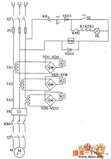
When any phase in three-phase power supply is missing because of some reason,the current transformer will lose the working current.The relay is released.The normally open contacts are disconnected.The AC contactor KM is released after power cut-off.It protects the electric motor from damage as the lose of phase.If the electric motor M is heating as the load is too heavy,the working current will increase.When the working current is beyond the set value,the thermal relay will take action.The normally closed contacts will disconnect.The AC contactor KM is released after power cut-off.Then you can cut off the working power supply of electric motor M.In order not to break down the electric motor because of overload . (View)
View full Circuit Diagram | Comments | Reading(1112)
the circuit of the temperature and humidity automatic controller (2)
Published:2011/6/21 6:21:00 Author:Ariel Wang | Keyword: temperature, humidity , automatic controller
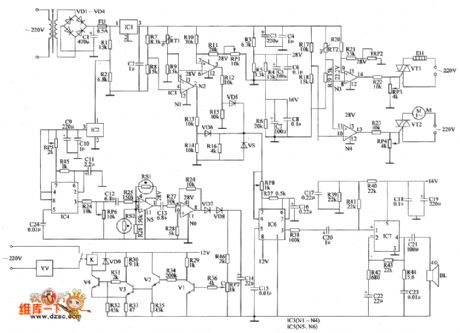
The 200V AC voltage is reduced by T,commutated by VD1~VD4,filtered by C1.Then it generates 45V DC voltage.One part of the voltage is regulated by IC1.Then it becomes +40V.It is branched by R3~R6,filtered by C5~C8.It generates +28V voltage and +16V voltage.The +28V voltage is for IC3 and IC5.The +16V voltage is for IC7.The other part of the voltage is brached by R1 and R2,regulated by C9,filtered by C10.It generates 12V DC voltage.It is the working voltage for IC4,IC6,VI~V4 and K.The +25.8V voltage is the reference voltage .It is the upper limit temperature of the temperature deviation alarm circuit.The +20V voltage is the reference voltage.It is the lower limit temperature of the temperature deviation alarm circuit. (View)
View full Circuit Diagram | Comments | Reading(531)
| Pages:57/164 At 204142434445464748495051525354555657585960Under 20 |
Circuit Categories
power supply circuit
Amplifier Circuit
Basic Circuit
LED and Light Circuit
Sensor Circuit
Signal Processing
Electrical Equipment Circuit
Control Circuit
Remote Control Circuit
A/D-D/A Converter Circuit
Audio Circuit
Measuring and Test Circuit
Communication Circuit
Computer-Related Circuit
555 Circuit
Automotive Circuit
Repairing Circuit