
Automotive Circuit
Index 58
the circuit of the humidity controller(2)
Published:2011/6/22 7:14:00 Author:Ariel Wang | Keyword: humidity , controller
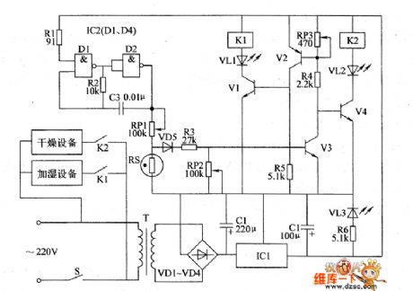
The resistence of RS changes when the humidity changes.When the environment humidity level decreases,the resistence of RS increases.The voltage of VS's base electrode increases.When the voltage of V3's base electrode is beyond 0.7V,V3 is conducted.V2 and V1 are conducted.V4 is stopped.K1 is conducted to pull in.The normally open contacts are connected.The humidifying equipment is conducted to work.At the same time,VI.1 is lighted.It indicates the humidifying equipment is working.When the humidity level increases,the resistence of RS decreases.The voltage of VS's base electrode decreases.When the voltage of Y3's base electrode is lower than 0.7V,V3 stopped.V4 is conducted.K2 is conducted to pull in.The normally open contacts are connected.The drying equipment is conducted to work.At the same time VL2 is lighted.V1 and V2 are stopped.K1 is released.
(View)
View full Circuit Diagram | Comments | Reading(443)
the automatic LED circuit of the chicken farm(3)
Published:2011/7/3 9:54:00 Author:Ariel Wang | Keyword: automatic, LED , chicken farm
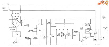
When the mains switch S gets through,the 220V AC voltage is reduced by T,commutated by VD1~VD4,filtered by C1 and regulated by IC1.Then it provides +12V voltage as the working power supply for IC2.When it's dark outside,the resistence of RC is increased.The voltage from pin-2 and pin-6 of IC2 becomes low level.The in-circuit of IC2 is turned over.The pin-3 output high level.IC3 is conducted to work.The pin-3 outputs high level.V1 and V2 are conducted.The LED and the light sensitive transistor work.VT is triggered to conduct.KM is conducted to pull in.The normally open contacts are connected.EL is conducted to be lighted.
(View)
View full Circuit Diagram | Comments | Reading(494)
the circuit of fish breeding oxygen gaining controller
Published:2011/6/17 6:53:00 Author:Ariel Wang | Keyword: fish breeding, oxygen gaining, controller
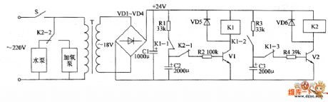
+24V voltage charges C2 by normally-closed contact R2 and K1.When the voltage of C2 reaches a certain value,transistor V1 is conducted.Relay K1 is pulled in.The normally-open contact K1-2 get through.+24V voltage charges C3 by the contacts of R3 and K1-2.At the same time,the normally-closed contact K1-1 is disconnected.C2 stops charging. The voltage of C2 discharges by R2.V1 stays conducted.K1 stays pull-in.When the voltage of C3 reaches a certain level,V2 is conducted.K2 pulls in.The normally-closed contact K2-1 is disconnected.It cuts off discharge circuit of C2.V1 stops.K1 is released.C2 starts charging again.
(View)
View full Circuit Diagram | Comments | Reading(420)
the circuit of the alarm for temperature monitor
Published:2011/6/17 8:13:00 Author:Ariel Wang | Keyword: alarm, temperature monitor
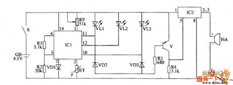
When the mains swith S gets through,battery CB provides 4.5V working power for the circuit of the whole machine.RT is used for detecting environment temperature.The resistence is decreasing when the temperature is increasin.The voltage of IC1's pin-2 is changing while the resistence of RT is changing.RP is used for setting the temperature of the monitor.When the environment temperature is right(within the set temperature) and the electric potential of IC1's pin-2 is between high level and low level.It outputs low level from pin-12.It outputs high level from pin-10 and pin-11.VL2 is lighted.VL1 and VL3 are not lighted.Sound alarming circuit does not work.HA doesn't give a sound.
(View)
View full Circuit Diagram | Comments | Reading(408)
the circuit of alarm for temperature detecting
Published:2011/6/17 23:13:00 Author:Ariel Wang | Keyword: alarm, temperature detecting
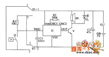
When S1 is at the position of 1 ,the alarm is being as over temperature alarm.When the controlled temperature is lower than the set temperature Q,the electrical contacts of Q are disconnected.IC stops working.BL doesn't give a sound.VL isn't lighted.When the controlled temperature is beyond the set temperature Q,the electrical contacts Q is conducted.IC is triggered to work.The acounstics signal which is output from the OUT end is amplified by V.BI gives alarm sound.VL is lighted.When S1 is at the position of 2 ,the alarm is being as low temperature alarm.When the controlled temperature is higher than the set temperature Q,the electrical contacts of Q are conducted.IC stops working.BL doesn't give a sound.VL is not lighted.
(View)
View full Circuit Diagram | Comments | Reading(462)
the circuit of loss-of-phase protecting relay for electric motor (5)
Published:2011/6/17 23:25:00 Author:Ariel Wang | Keyword: loss-of-phase, protecting, circuit , relay , electric , motor
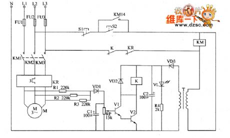
When starting button is pressed,the voltage between L2 and L3 go to AC contactor KM through Stop button 51,start push button 52 ,the normally-closed contact of relay K and contact of thermal relay KR.KM pulls in.The electric motor gets to work.It provides 12V DC voltage for relay-driven circuit(consist of V1,V2,VD2 and K) after it is reduced by T,commutated by VD3 and filtered by C2. At the same time,it lights up VL.When three-phase (L1,L2,L3) AC voltage is normal,the voltage is 0V between the plus terminal of VD1 (the Y-connected middle point) and zero line N.V1 is not conducted with V2.K is released.
(View)
View full Circuit Diagram | Comments | Reading(516)
FM transmitter 2KM circuit
Published:2011/7/6 7:03:00 Author:John | Keyword: FM transmitter
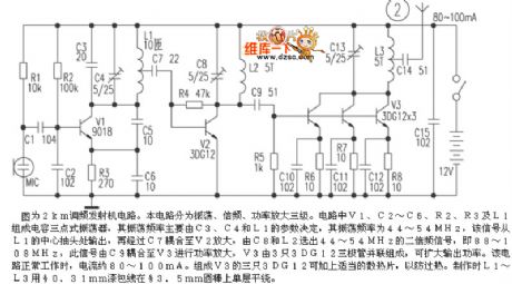
The figure shows the FM transmitter 2km circuit. The circuit is divided into three phases, which are the shock, frequency and power amplification. V1, C2 ~ C6, R2, R3, and L1 in the circuit form the three-point capacitance oscillator, whose oscillation frequency is mainly determined by parameters of the C3, C4 and L1. Its oscillation frequency is 44 ~ 54MHz. The relative signal is output from L1's center tap and then coupled to the V2 for amplification through C7. Then 44 ~ 54MHz second harmonic signal would be selected from C8 and L2, which equals to 88 ~ 108MHz. At this time, the signal is coupled to V3 power amplification through C9. And V3 is composed by three 3DG12 transistors in parallel, aiming to expand the output frequency.
(View)
View full Circuit Diagram | Comments | Reading(2436)
the circuit of phase failure protector for electric motor(3)
Published:2011/6/18 5:21:00 Author:Ariel Wang | Keyword: phase failure , protector, electric motor
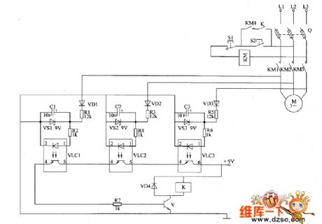
After the starting button is pressed,AC contactor KM is conducted to pull in.The normally open contacts KM1-KM4 do not get through.The electric motor M goes to work.If the three-phase AC power supply is normal,the LEDs inside VLC1-VLC3 are all lighted.The optical transistors are all conducted.V is saturated to conduct.K pulls in.The normally open contacts get through.When S2 is disconnected,KM could stay pull-in.If one of the phase in three-phase alternating-current supply is missing,the optical coupler in voltage detecting circuit is stopped.V couldn't conduct.K doesn't pull in.When S2 is disconnected,KM is no longer pull-in.The phase failure reaches the goal of automatic protection.
(View)
View full Circuit Diagram | Comments | Reading(1741)
The ChangFeng LieBao SUV engine ignition system circuit
Published:2011/7/6 1:24:00 Author:Christina | Keyword: ChangFeng, LieBao, SUV, engine, ignition system
The ChangFeng LieBao SUV engine ignition system circuit:
(View)
View full Circuit Diagram | Comments | Reading(500)
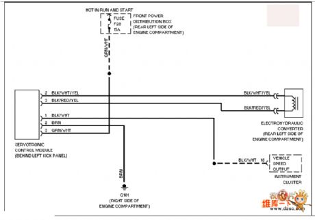
BMW electronic power steering system circuit
Published:2011/7/6 1:21:00 Author:Christina | Keyword: BMW, electronic power, steering system
View full Circuit Diagram | Comments | Reading(1019)
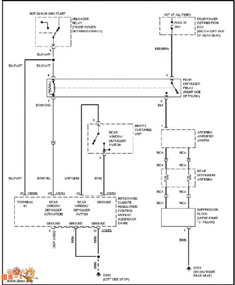
BMW defogger circuit
Published:2011/7/5 22:17:00 Author:Christina | Keyword: BMW, defogger
View full Circuit Diagram | Comments | Reading(459)
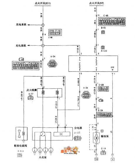
ChangFeng LieBao SUV 6G72 engine ignition system circuit
Published:2011/7/5 22:13:00 Author:Christina | Keyword: ChangFeng, LieBao, SUV, engine, ignition system

The ChangFeng LieBao SUV 6G72 engine ignition system circuit is as shown:
(View)
View full Circuit Diagram | Comments | Reading(891)
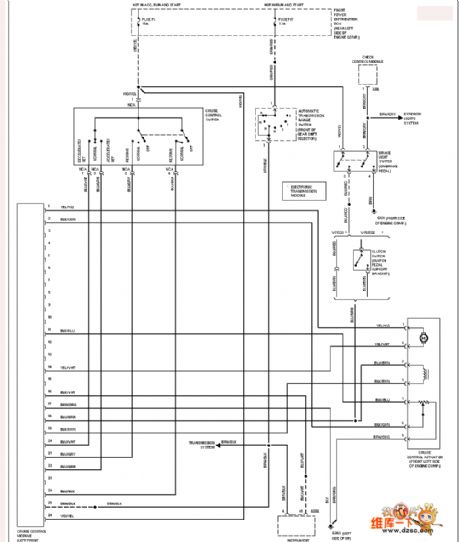
BMW cruise control circuit
Published:2011/7/5 22:14:00 Author:Christina | Keyword: BMW, cruise, control
View full Circuit Diagram | Comments | Reading(762)
BMW seat heating circuit
Published:2011/7/6 1:47:00 Author:Christina | Keyword: BMW, seat heating
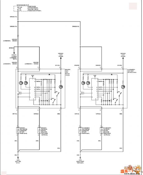
View full Circuit Diagram | Comments | Reading(524)
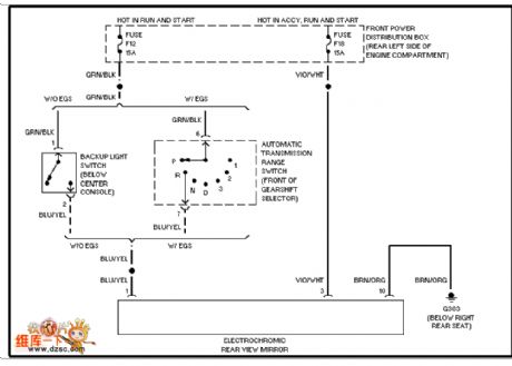
BMW automatic memory rearview mirror circuit
Published:2011/7/6 1:48:00 Author:Christina | Keyword: BMW, automatic memory, rearview mirror
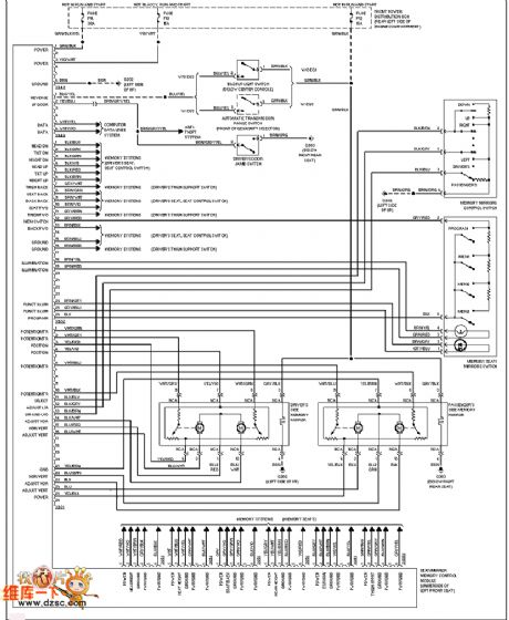
BMW automatic memory rearview mirror circuit
(View)
View full Circuit Diagram | Comments | Reading(493)
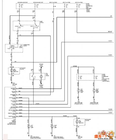
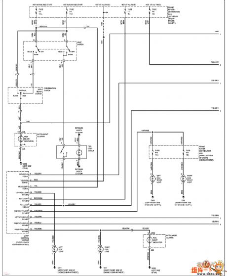
BMW (without the DRL1) headlamp circuit
Published:2011/7/6 1:28:00 Author:Christina | Keyword: BMW, DRL1, headlamp circuit
View full Circuit Diagram | Comments | Reading(440)
Buick century power distribution & grounding circuit
Published:2011/7/6 1:52:00 Author:Christina | Keyword: Buick century, power distribution, grounding
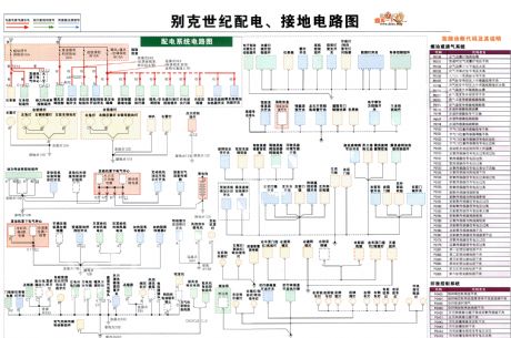
The Buick century power distribution & grounding circuit is as shown in the figure:
(View)
View full Circuit Diagram | Comments | Reading(400)
BMW (with the DRL1) headlamp circuit
Published:2011/7/6 1:27:00 Author:Christina | Keyword: BMW, DRL1, headlamp
View full Circuit Diagram | Comments | Reading(445)
BMW photosensitive discoloration rearview mirror circuit
Published:2011/7/6 1:55:00 Author:Christina | Keyword: BMW, photosensitive, discoloration, rearview mirror
View full Circuit Diagram | Comments | Reading(526)
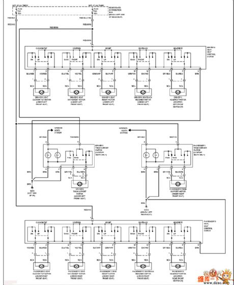
BMW electric seat circuit
Published:2011/7/6 1:57:00 Author:Christina | Keyword: BMW, electric seat
View full Circuit Diagram | Comments | Reading(464)
| Pages:58/164 At 204142434445464748495051525354555657585960Under 20 |
Circuit Categories
power supply circuit
Amplifier Circuit
Basic Circuit
LED and Light Circuit
Sensor Circuit
Signal Processing
Electrical Equipment Circuit
Control Circuit
Remote Control Circuit
A/D-D/A Converter Circuit
Audio Circuit
Measuring and Test Circuit
Communication Circuit
Computer-Related Circuit
555 Circuit
Automotive Circuit
Repairing Circuit