
Automotive Circuit
Index 41
The 2.0L(L34) engine idle speed air control, oil position switch and pressure display circuit
Published:2011/7/20 3:38:00 Author:Borg | Keyword: idle speed, oil position switch
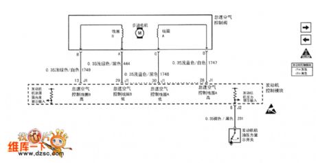
Figure1 The 2.0L(L34) engine idle speed air control, oil position switch and pressure display circuit of Shanghai GM Buick-Regal
(View)
View full Circuit Diagram | Comments | Reading(480)
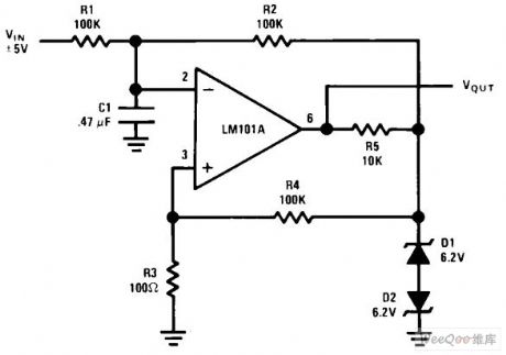
Pulse width modulator circuit
Published:2011/7/20 0:45:00 Author:Fiona | Keyword: Pulse width, modulator
View full Circuit Diagram | Comments | Reading(622)
Multiplier of capacitor circuit
Published:2011/7/20 0:42:00 Author:Fiona | Keyword: capacitor, multiplier
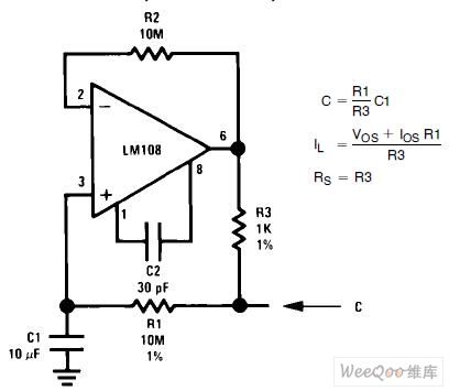
Capacitor's multiplier circuit is shown as above:
(View)
View full Circuit Diagram | Comments | Reading(1256)
Polo Power Steering System Circuit
Published:2011/7/26 10:16:00 Author:Robert | Keyword: Polo, Power, Steering System

The picture shows the Polo power steering system circuit.
In this circuit the D is ignition/starting switch. The G250 is power steering sensor. The J285 is the dashboard ECU with monitor. The J500 is power steering ECU. The J519 is car network ECU. The K92 is assistance mechanism signal lamp. The S164 is fuse. The SB7 is fuse 7 on the fuse holder. The T2B is plug with 2 holes. The T3e is plug with 3 holes. The T4r, T4L are plugs with 4 holes. The T11a is plug with 11 holes. The T11b is plug with 11 holes. The T16a is plug with 16 holes. The T32a is plug with 32 holes. The V119 is steering hydraulic pump. And so on. (View)
View full Circuit Diagram | Comments | Reading(3783)
Golf Bora Car Light Circuit
Published:2011/7/24 8:26:00 Author:Robert | Keyword: Golf, Bora, Car, Light
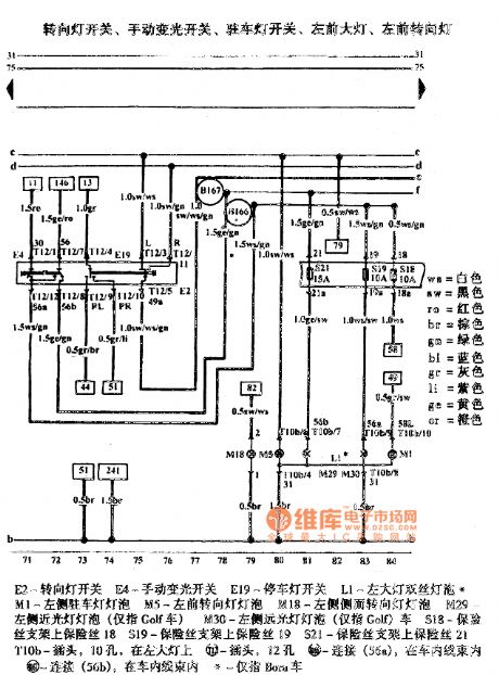
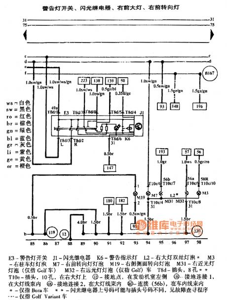
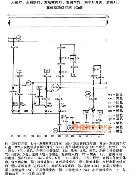
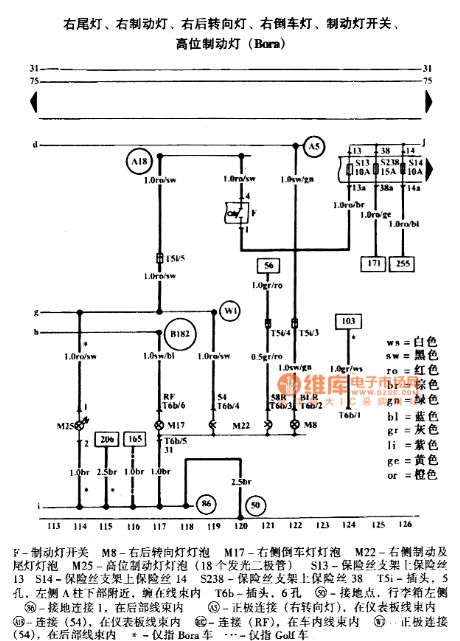
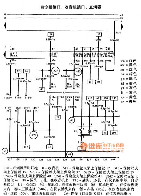
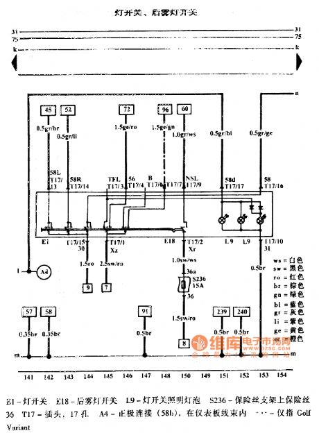
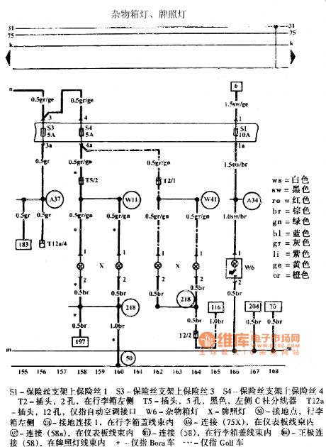
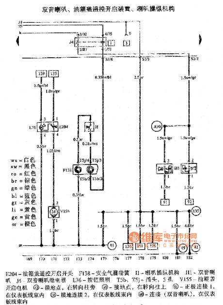
These pictures show the Golf Bora car light circuits.
The picture 1 shows the turning lamp switch, manual dimmer switch, parking lamp switch, left head lamp, left head turning lamp.
The picture 2 shows the warning lamp switch, flash relay, right head lamp, right head turning lamp.
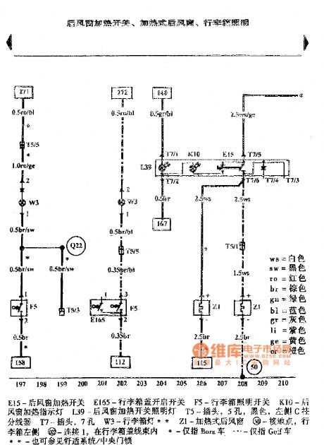
The picture 3 shows the left rear lamp, left brake lamp, left rear turning lamp, left reversing light, reversing light switch, rear fog lamp, high brake lamp bulb (Golf).
The picture 4 shows the right rear lamp, right brake lamp, right rear turning lamp, right reversing light, brake lamp switch, high brake lamp (Bora).
The picture 5 shows the self-diagnostic interface, radio interface, cigarette lighter.
The picture 6 shows the lamp switch, rear fog lamp switch.
The picture 7 shows the sundries box lamp, license plate lamp.
The picture 8 shows the dual-tone horn, fuel tank lid remote-control opening device, horn operating mechanism.
And so on. (View)
View full Circuit Diagram | Comments | Reading(560)
Golf Bora Instrument Cluster Circuit
Published:2011/7/25 10:17:00 Author:Robert | Keyword: Golf, Bora, Instrument, Cluster
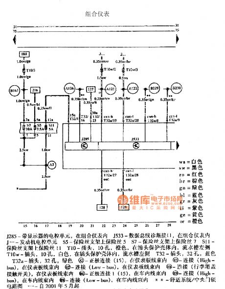
The pictures show the Golf Bora instrument cluster circuits.
The first picture shows the instrument cluster circuit.
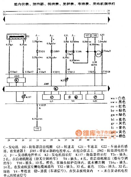
The second picture shows the instrument cluster, anti-theft circuit, tachometer, odometer, speedometer, power generator indicating lamp.
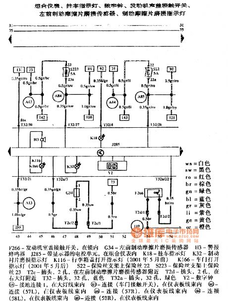
The third picture shows the instrument cluster, trailer indicating lamp, digital clock, engine compartment lid contacting switch, left-front brake friction plate wear sensor, brake friction plate wear indicating lamp.
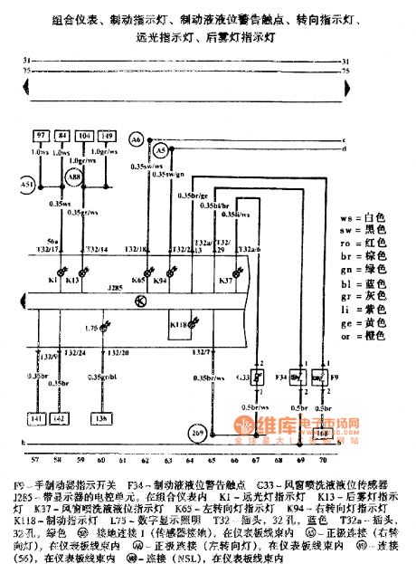
The fourth picture shows the instrument cluster, brake indicating lamp, brake liquid level alarm contactor, turning indicating lamp, high beam indicating lamp, rear fog indicating lamp. (View)
View full Circuit Diagram | Comments | Reading(818)
Golf Bora Automatic Anti-Glare Car Inside Rearview Mirror And Rain Sensor Circuit
Published:2011/7/25 19:54:00 Author:Robert | Keyword: Golf, Bora, Automatic, Anti-Glare, Car, Rearview Mirror, Rain Sensor
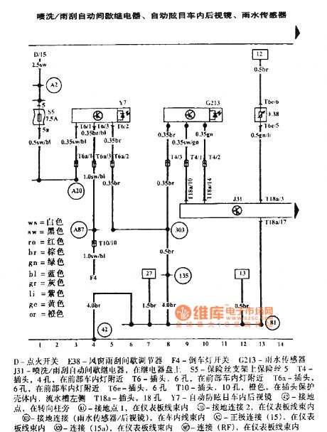
The pictures show the Golf Bora automatic anti-glare car inside rearview mirror and rain sensor circuits.
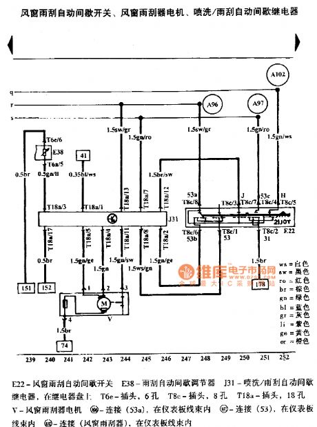
The first picture shows the spraying/wiper automatic intermittent relay, automatic anti-glare car inside rearview mirror, rain sensor.
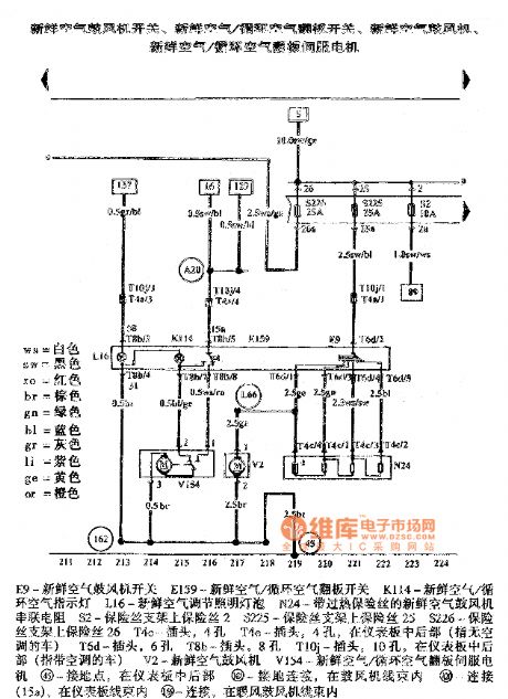
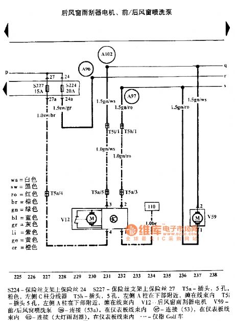
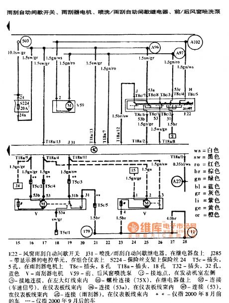
The second picture shows the wiper automatic intermittent switch, wiper electric motor, spraying/wiper automatic intermittent relay, front/rear windshield spray pump.
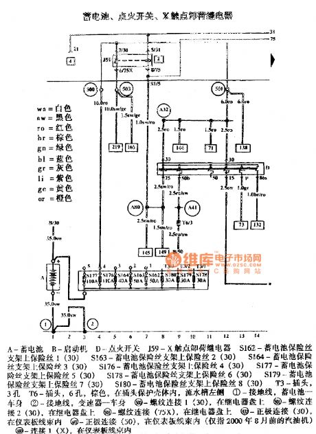
The third picture shows the battery, ignition switch, X contactor unloading relay. (View)
View full Circuit Diagram | Comments | Reading(1424)
Golf Bora Telephone Circuit
Published:2011/7/26 7:09:00 Author:Robert | Keyword: Golf, Bora, Telephone
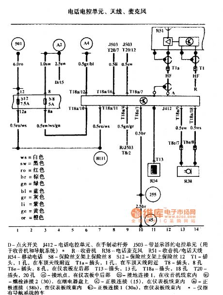
The picture shows the Golf Bora telephone circuit.
The picture shows the telephone electrical control unit, antenna, microphone. The D is ignition switch. The J412 is telephone electrical control unit which is beside the hand brake lever. The J503 is the electrical control unit with monitor (it is used for radio and navigation system). The R is radio. The R38 is telephone micrphone. The R51 is radio/telephone antenna. The R54 is mobile phone. The S8 is the fuse 8 on the fuse holder. The S12 is the fuse 12 on the fuse holder. The T1 is plug with 1 hole which is beside the car roof antenna. The Tla is plug with 1 hole which is beside the car roof antenna. The T8 is plug with 8 holes. The T8e is plug with 8 holes which is in the left-rear dashboard. And so on. (View)
View full Circuit Diagram | Comments | Reading(469)
Golf Bora Radio Circuit
Published:2011/7/26 9:54:00 Author:Robert | Keyword: Golf, Bora, Radio
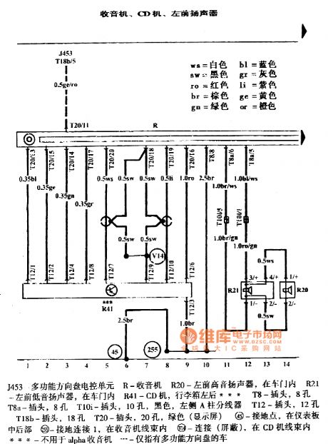
The pictures show the Golf Bora radio circuits.
The first picture shows the radio, CD player, left-front speaker.
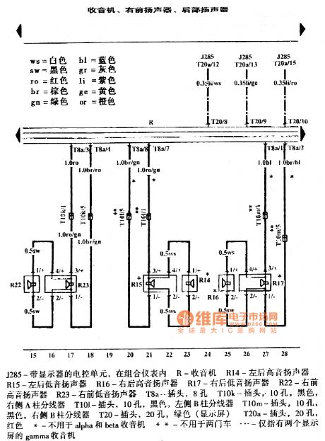
The second picture shows the radio, right-front speaker, rear speaker.
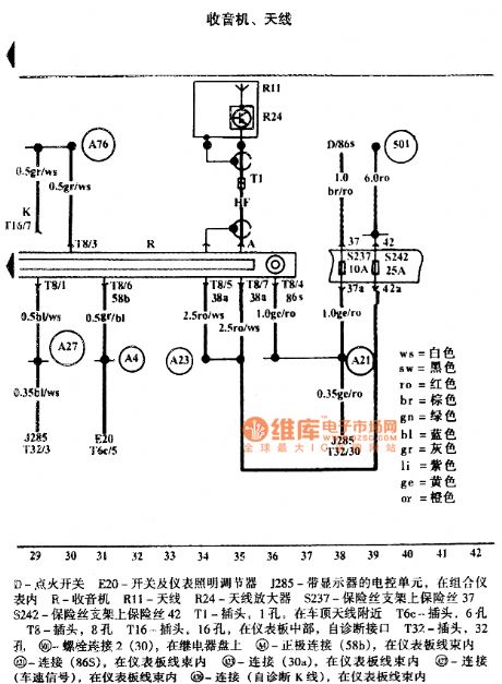
The third picture shows the radio and antenna. In the picture the part D is ignition switch. The E20 is switch and instrument lighting regulator. The J285 is an ECU with monitor inside the instrument cluster. The R is radio. The R11 is antenna. The R24 is antenna amplifier. The S237 is the fuse on the fuse holder 37. The S242 is the fuse on the fuse holder 42. The T1 is a plug with 1 hole near the car roof antenna. The T6c is plug with 6 holes. The T8 is plug with 8 holes. The T16 is plug at the middle of the dashboard with the self-diagnosis interface. The T32 is plug with 32 holes. And so on. (View)
View full Circuit Diagram | Comments | Reading(612)
Buick GL8 Car ABS Stopping Lamp Switch Input And Torque Circuit
Published:2011/7/24 10:09:00 Author:Robert | Keyword: Buick, GL8, Car, ABS, Stopping Lamp, Switch, Input, Torque
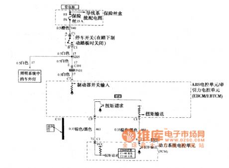
The picture shows the Buick GL8 car ABS stopping lamp switch input and torque circuit. (View)
View full Circuit Diagram | Comments | Reading(421)
Cheetah SUV Automatic Transmission Circuit
Published:2011/7/26 8:08:00 Author:Robert | Keyword: Cheetah, SUV, Automatic, Transmission
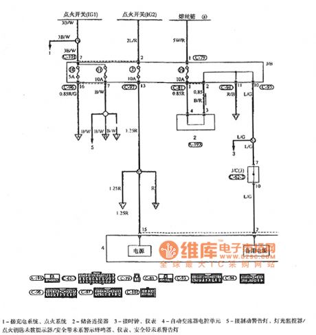
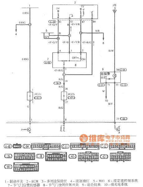
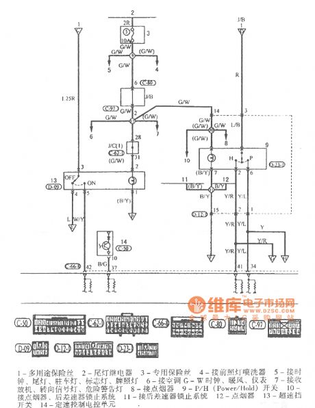
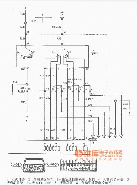
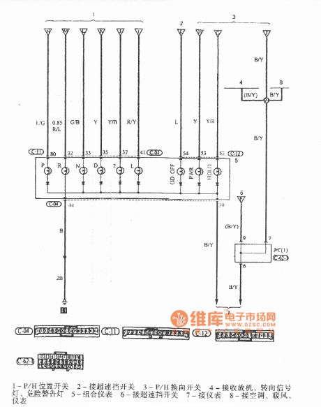
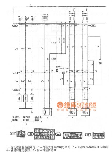
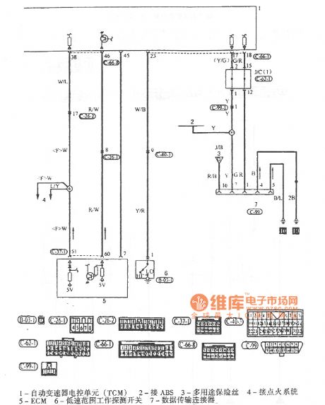
The pictures show the Cheetah SUV automatic transmission circuits.
In picture 1 the part 1 is connected to the charging system and ignition system. The part 2 is reserve connector. The part 3 is connected to clock and instruments. The part 4 is automatic transmission ECU. The part 5 is connected to brake alarm lamp, the light monitor, ignition key not-pulling reminder, seat belt not-tying alarm buzzer, instrument, seat belt not-tying alarm lamp.
In picture 2 the part 1 is brake switch. The part 2 is ECM. The part 3 is multi-purpose fuse. The part 4 is connected to the brake lamp. The part 5 is MFI. The part 6 is connected to constant speed control system. The part 7 is throttle position sensor. The part 8 is throttle full-closing position switch. The part 9 is instrument cluster. The part 10 is connected to charging system.
In picture 3 the part 1 is multi-purpose fuse. The part 2 is rear lamp relay. The part 3 is special fuse. The part 4 is connected to front lamp washers. The part 5 is connected to clock, rear lamp, parking lamp, logo lamp, license plate lamp. The part 6 is connected to air conditioner. The part 7 is connected to radio, turning signal lamp, danger alarm lamp. And so on. (View)
View full Circuit Diagram | Comments | Reading(526)
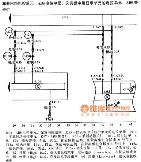
Polo ABS Circuit
Published:2011/7/26 8:26:00 Author:Robert | Keyword: Polo, ABS
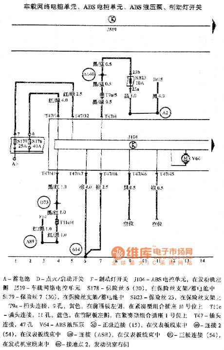
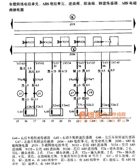
The pictures show the Polo ABS circuit.
The first picture shows the car network ECU, ABS ECU, ABS hydraulic pump, brake lamp switch.
The second picture shows the car network ECU, ABS ECU, oil-feed pump, oil drain pump, rotationl speed sensor, ABS electromagnetic pump relay.
The third picture shows the car network ECU, ABS ECU, dashboard ECU with display unit, ABS alarm lamp. In the picture the J104 is ABS ECU which is at the left side of engine. The J285 is dashboard ECU with display unit. The J519 is car network ECU. The K47 is ABS alarm lamp. The K61 is hand brake lamp. And so on. (View)
View full Circuit Diagram | Comments | Reading(1603)
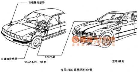
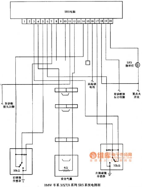
BMW SRS component location circuit diagram
Published:2011/7/26 3:12:00 Author:Ecco | Keyword: BMW , SRS component location
View full Circuit Diagram | Comments | Reading(468)
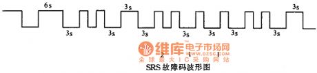
BMW trouble code waveform circuit diagram
Published:2011/7/26 3:16:00 Author:Ecco | Keyword: BMW , trouble code waveform
View full Circuit Diagram | Comments | Reading(492)
BMW Fault code display process circuit diagram
Published:2011/7/26 3:15:00 Author:Ecco | Keyword: BMW , Fault code, display process
View full Circuit Diagram | Comments | Reading(594)
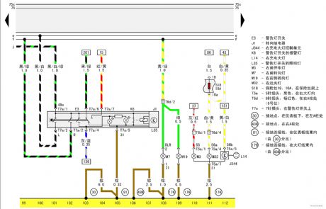
Turning relay warning light switch, right front lamp of Passat GSi circuit diagram 2
Published:2011/7/25 22:01:00 Author:Ecco | Keyword: turning relay , warning light switch, right front lamp , Passat GSi
View full Circuit Diagram | Comments | Reading(556)
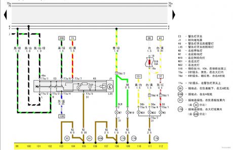
Turning relay warning light switch, right front lamp of Passat GSi circuit diagram 1
Published:2011/7/25 22:02:00 Author:Ecco | Keyword: Turning relay , warning light switch, right front lamp , Passat GSi
View full Circuit Diagram | Comments | Reading(508)
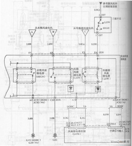
Hyundai Sonata car cooling system circuit diagram 2
Published:2011/7/25 22:09:00 Author:Ecco | Keyword: Hyundai Sonata car , cooling system
View full Circuit Diagram | Comments | Reading(749)
Automotive Fuel Monitor Five
Published:2011/7/17 5:56:00 Author:Felicity | Keyword: Automotive Fuel Monitor
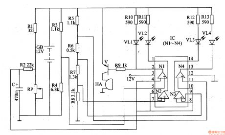
The circuit consists of oil level monitoring circuit, the oil level indicating circuit and lacking fuel alarm circuit.
Oil level monitoring circuit consists of automotive fuel tank float potentiometer RP, resistors Rl, R2 and capacitor C.
The oil level indicating circuit consists of R3-R8, RlO-R13, LED VL1-VL4 and quad op amp IC IC (Nl-N4).
Lacking fuel alarm circuit consists of resistor R9, transistor V and buzzer HA.
The voltage divider circuit consist of R3-R8 and the circuit provides standard oil level voltage for the non-inverting terminal of N1-N4 inside IC; The voltage divided by R1 and RP and then put on to inverting terminal of N1-N4 through R2 as the oil amount sample voltage.
When the fuel tank is full of oil, the resistance of RP is at its lowest and N1, N3, N4 output high level voltage, VL2 output low level voltage. And the yellow LED VL2 is on indicating the fuel tank is full.
When the tank is 3/4 full, N3 also output low level voltage to make green led VL3 on.
When the tank is 1/2 full, N4 also output low level voltage to make green led VL4 on.
When the tank is 1/4 full, N1 also output low level voltage to make red led VL1 and V on. And the beeper beeps to remind the driver to refuel. (View)
View full Circuit Diagram | Comments | Reading(779)
Automotive Fuel Monitor Two
Published:2011/7/17 6:04:00 Author:Felicity | Keyword: Automotive Fuel Monitor
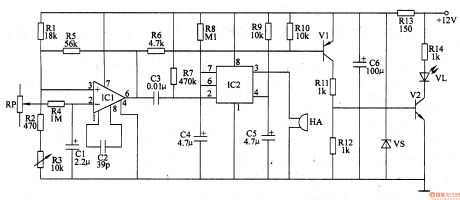
The circuit consists of comparator, the monostable flip-flop and warning lamp circuit. (It is showed in picture 7-59.)
Comparator consists of divider circuit (by the resistors Rl-R3 form) and integrated operational amplifier circuit ICl.
The monostable flip-flop consists of time-base integrated circuit IC2 and the peripheral components.
Warning lamp circuit consists of transistor Vl, V2, and light-emitting diode VL.
Pin 2 (inverting terminal) of IC1 is connected to the center head of RP,the potentiometer, through R4.
When the fuel is enough, pin 6 of IC 1is at high level ,V1 and V2 both cut off.
When the amount of fuel is below a certain value, pin 6 is at low level. And then V1 and V2 is on to light up LED VL; The monostable flip-flop inside IC2 flip, changing from steady-state into transient-state. Pin 3 of IC3 is at high level,and the beeper HA works.
When C3 is end of charge, IC is at steady-state again. Pin 3 is at low level and HA stops. But LED VL shines until the fule tank is refilled. (View)
View full Circuit Diagram | Comments | Reading(507)
| Pages:41/164 At 204142434445464748495051525354555657585960Under 20 |
Circuit Categories
power supply circuit
Amplifier Circuit
Basic Circuit
LED and Light Circuit
Sensor Circuit
Signal Processing
Electrical Equipment Circuit
Control Circuit
Remote Control Circuit
A/D-D/A Converter Circuit
Audio Circuit
Measuring and Test Circuit
Communication Circuit
Computer-Related Circuit
555 Circuit
Automotive Circuit
Repairing Circuit