
Automotive Circuit
Index 53
CVD-1--the decoding integrated circuit of SVCD player
Published:2011/7/12 3:57:00 Author:Borg | Keyword: decoding, integrated circuit, SVCD player
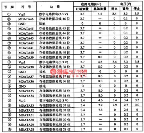
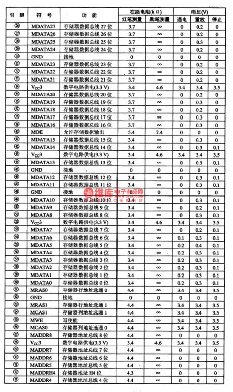
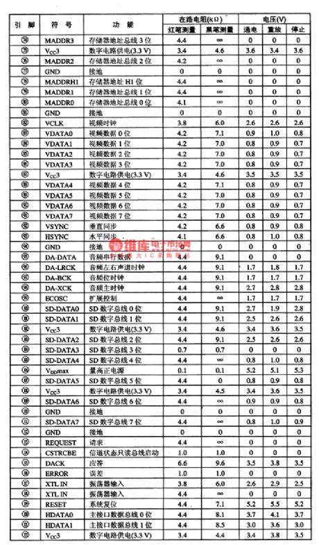
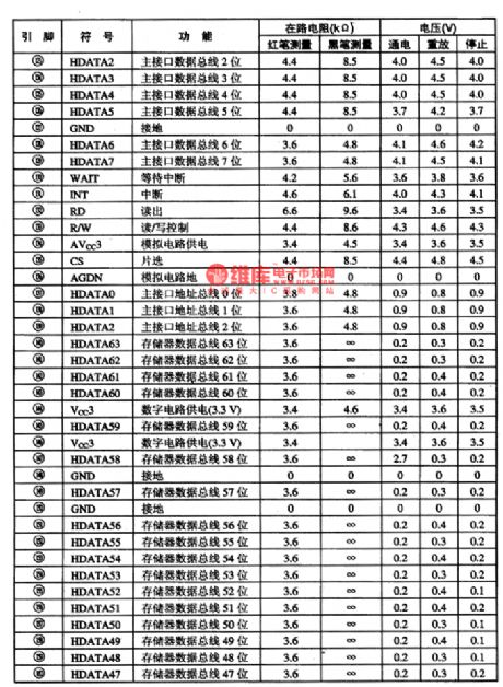
CVD-1 is the decoding integrated circuit of SVCD player, which is used in Changhong and other SVCD players as the decoding circuit.1.function featuresCVD-1 contains the memory, controller, main drive logic control, programme spreading decoder, OSD decoding, layer decoding, MPEG video decoder, MPEG audio decoder, video mixer, synchronized generator, digital audio connector and other circuit unit.2.pin functions and dataCVD-1 is in 160-pin square package structure, whose pin functions and data are listed in table 1.
(View)
View full Circuit Diagram | Comments | Reading(500)
Beijing Cherokee wire cross-section conventional and regular circuit diagram
Published:2011/5/6 4:07:00 Author:Rebekka | Keyword: Beijing Cherokee wire, cross-section conventional and regular
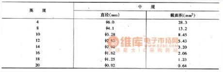
Specify the wire cross-sectional area and color. Figure shows 31-8 Power Configuration in the left side of the first line labeled 12 Red , 12 Orange , where red and orange color shows the wire. 12 is a cross-sectional area wire regular code, the main wiring conventional and regular are shown in figure1. (View)
View full Circuit Diagram | Comments | Reading(375)
Toyota Land Cruiser 70 light off-road vehicle power starting horn rearview mirror principle circuit diagram
Published:2011/5/9 3:15:00 Author:Rebekka | Keyword: Toyota Land Cruiser 70, light off-road vehicle power

l ofbattery; 2 fusible switch line fire switch; 4 start relay; 5 starter; 6 cold start nozzle; 7 the nozzle cold start timer switch; 8 speaker; 9 horn button; 10 remote control mirror switch; 11 left rear view mirror motor; 12 right-rear view mirror; 175 winch main relay; 76 bulb check relay; 37 heat timer; 55 air-conditioning (WC) amplifier; 151 turning and hazard warning switch; F21 ACC ignition switch forconnection from the client. (View)
View full Circuit Diagram | Comments | Reading(1750)
Toyota Land Cruiser 70 light off-road vehicle auxiliary instrument principle circuit diagram
Published:2011/5/9 3:20:00 Author:Rebekka | Keyword: Toyota Land Cruiser 70, light off-road vehicle
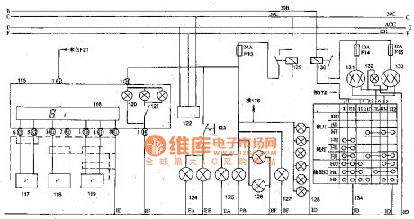
Toyota Land Cruiser 70 light off-road vehicle auxiliary instrument principle circuit diagram.
115 auxiliary instrument panel; 116 digital thermometer; 117 temperature sensor; 118 room temperature sensor 1; 119 room temperature sensor 2; 120 auxiliary instrument panel lighting; 121 auxiliary instrument panel light switch; 122 test plugs; 123 front fog lamp switch; 124 front left and right fog lamps; 125 wide front headlights; 126 taillight; 127 license plate light; 128 instrument lights; 129 taillight relay; headlamp relay; 131 left headlight; 132 light beam; 133 right headlight; 134 light control switch; F2l connection from the ignition ACC fuse switch; 172 headlamp beam control switch; 178digital electric clock; (View)
View full Circuit Diagram | Comments | Reading(1667)
Toyota Land Cruiser 70 light off-road vehicle headlamp beam adjustment winches and clock circuit diagram
Published:2011/5/8 12:36:00 Author:Rebekka | Keyword: Toyota Land Cruiser 70 , light off-road vehicle, headlamp beam adjustment
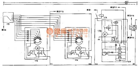
Toyota Land Cruiser 70 light off-road vehicle headlamp beam adjustment winches and clock circuit diagram.
172 headlamp beam control switch; 173 left headlight beam control actuators; 174 right-headlight beam control actuators; 175 winch main relay; 176 winch solenoid switch and motor; 177 winch control switch; 178 digital electric clock; 134 light control switch; F13 taillight relay; 129 battery; F11 IG1 fuse column connected by the ignition switch ; F16 connection from the battery positive 30C line fuse; F13 129 fuse connects from the taillight relay. (View)
View full Circuit Diagram | Comments | Reading(1658)
Mitsubishi Pajero light off-road vehicle circuit instrument panel wiring harness configuration circuit diagram
Published:2011/5/9 2:49:00 Author:Rebekka | Keyword: Mitsubishi Pajero , Light off-road vehicle

01 fuse group; 02 speaker (left); 04 large rear door lock switch; 05 heostat; 06 rear defroster switch box; 08,09 comprehensive instrument; 11 rear wiper and washer switch; 12,13 oil pressure gauge; 14 integrated instrument lighting; 15 the integrated instrumentation and wiring; 16 integrated instrument lighting; 17,18 voltage meter; 19 heating relay; 20,21 empty wither machine wiring A and the former wiring; 22 speaker (right); 23 dedicated fuse; 24 hood and front wiring; 25 hood wiring connection; 27 heating wiring; 28 front door and front wiring; 29 heating fan motor; 30,31 thermal switch; 32 power relay B; 33 air conditioning electromechanical road; 34 power relay A; 35 air conditioner switch; 36 minute; 37 heating fan switch; 38 ashtray light; 39 spare cable connector; 41 parking brake switch; 44 heating control lighting; 46 lights that smoke detectors; 47 meter wiring wiring wiring wiring and the former; 48 heating fan switch; 50,51 light switch; 52 the fire switch; 53 stop light switch; 54,55 withfront door cable wiring and wiring connections before; 56 flash device; 57 power window relay; 58 wiper relay; 59 headlight washer relay; 64 radio; 65 tape recorder; 66 air conditioner cable wiring and wiring connections; 68,69 wiper. (View)
View full Circuit Diagram | Comments | Reading(8339)
The turning signal, danger signal and internal light (ceiling lamp) circuits of Nanjing Iveco light car
Published:2011/7/12 22:46:00 Author:Borg | Keyword: turning signal, danger signal, internal light, light car
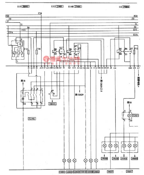
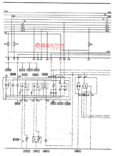
(7) turning signal and danger alarm signal(see as figure 7)The turning lamp switch 54033 (in the grouped switch) is powered by the turning flash relay E15(58000), and left head turning lamp 32002, left side turning lamp 33001, left rear turning lamp 34000(in the grouped lamps) are installed at the side of the turning lamp switch , and the 3 corresponding lamps on the right are installed at other side of the turning lamp, whose part numbers are the same with the ones of the left side. Danger alarm lamp switch 52302 and the turning lamp switch are in parallel connection, and their input powers are also from the flasher E15(58000), the output currents can also be delivered to the left and right turning lamps.
(View)
View full Circuit Diagram | Comments | Reading(454)
Mitsubishi Pajero sport utility vehicle circuit cambodia hood off-line configuration circuit diagram
Published:2011/5/9 2:34:00 Author:Rebekka | Keyword: Mitsubishi Pajero, sport utility vehicle

01 main fusible line; 02,03 fusible wire; 04,054 wheel drive light switch; 06,07 reversing lights and four lights and cords for wiring processing unit integrated; 08,09 backup light switch; l0 air conditioners; 11windshield wiper motor; 14 former wire processing. Reversing lights and the four fixed light wiring processing; 15,16 special fusible wire (power windows circuit); 17 former air conditioner wiring wiring to deal with comprehensive treatment C; 18 forheadlight washer ; 20 light switch relay; 21 front combination lamp (left); 22 dedicated fuse (high beam circuit); 23 headlamp (left); 24,25,26,27 speaker; 28,29.30 little fire coil; 31 fuel cut off solenoid valve; 32 magnetic clutch; 33 , 34 AC generator; 35 oil pressure gauge oil pressure switch devices; 36,37 low-voltage switching; 38 ofheadlamp (right); 39 former air conditioner wiring wiring to deal with treatment B synthesis; 40 the combination of switch (right); 45 front washer motor; 47,48 starter; 49 water temperature sensor; 50 forwater temperature switch; 71 power relay; 72 condenser fan motor. (View)
View full Circuit Diagram | Comments | Reading(3053)
The ceiling lamp, internal lamp, warm air and signal circuit of Nanjing Iveco light car
Published:2011/7/12 21:57:00 Author:Borg | Keyword: ceiling lamp, Nanjing Iveco, light car
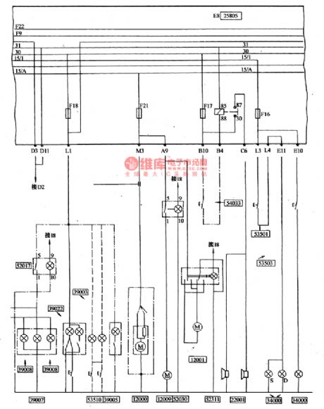
(8) wiper, washer, cigarette and radio (see as figure 9)Water jet gear is controlled by key 54033, the current comes from F20, at the same time, the relay circuit and wash pump are powered by it, after the water spray, as the capacitor can release power slowly in some time, which makes the relay contactor pull in for some time, the action of wiping is done for times and the water marks (see as figure 9).The current of the radio and cigarette is from F18 of wire 30, and it comes out from the L plug of the central connection box (L2 terminal).
(View)
View full Circuit Diagram | Comments | Reading(401)
The generator attachment circuit of the Nanjing Iveco light car
Published:2011/7/12 22:49:00 Author:Borg | Keyword: generator attachment, light car
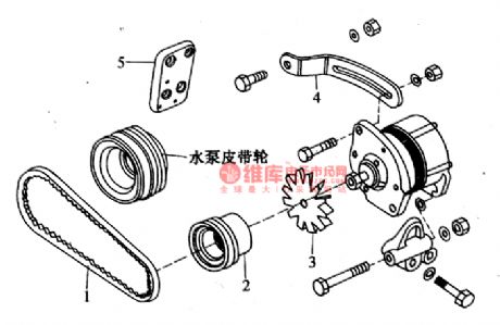
The generator attachmentdiagram of the Nanjing Iveco light car(see as figure 12).
(View)
View full Circuit Diagram | Comments | Reading(370)
The battery, loudspeaker and power supply switch circuit of Nanjing Iveco light car
Published:2011/7/12 21:44:00 Author:Borg | Keyword: power supply, Nanjing Iveco, light car
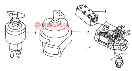
(12) the outline of the battery, loudspeaker and power supply (see as figure 14)
(View)
View full Circuit Diagram | Comments | Reading(362)
The central door lock circuit of Santana 2000 (gasoline injection engine)
Published:2011/7/12 23:00:00 Author:Borg | Keyword: central door lock, Santana 2000
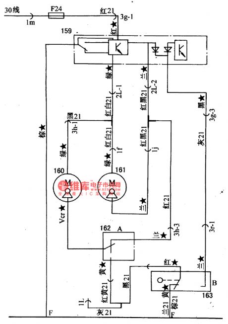
Figure: The central door lock circuit of Santana 2000Li(gasoline injection engine)159-central lock device; 160-right door lock motor; 161-rear shell lock motor; 162-right door shutting micro switch; 163-door close micro switchWhen the key of the driver door is pushed or pulled, or the door is opened (or closed) by the key, other car doors can also be controlled synchronously, and other keys can control the corresponding lockers (open or close), whose functions are irrelevant with the igniting switch. (View)
View full Circuit Diagram | Comments | Reading(550)
The Santana 2000 power window circuit
Published:2011/7/13 21:12:00 Author:Borg | Keyword: Santana 2000, power window

Figure 1. The Santana 2000 power window circuit (gasoline injection engine)143-left door glass direction switch; 144-left door glass direction motor; 145-left door glass direction relay; 146-door window direction lighting lamp; 147-door window direction lighting lamp resistor; 148-right door window direction switch; 149-glass direction lighting lamp; 150-glass direction lighting lamp relay; 151-right door window direction motor; 152-heat electric breaker(20A); 153-glass direction motor time relay (View)
View full Circuit Diagram | Comments | Reading(415)
CD9632--the field scanning output integrated circuit
Published:2011/7/13 22:10:00 Author:Borg | Keyword: field scanning, integrated circuit
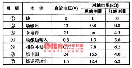
1.function featuresCD9632 contains the field scanning motivation signal amplifier circuit, field scanning output power amplifier circuit, field blanking pulse generating circuit, field scanning pump power supply circuit and other additional circuits.2.pin functions and dataCD9632 is in 7-pin single in-line package, whose pin functions and data are listed in table 1. The data in the table are from the test results of Konka T2587(1) large screen color TV sets.
Table 1. Pin functions and data of CD9632 (View)
View full Circuit Diagram | Comments | Reading(407)
The room lamp and signal circuit of Santana 2000 (gasoline injection engine)
Published:2011/7/13 21:40:00 Author:Borg | Keyword: room lamp, signal circuit, Santana 2000
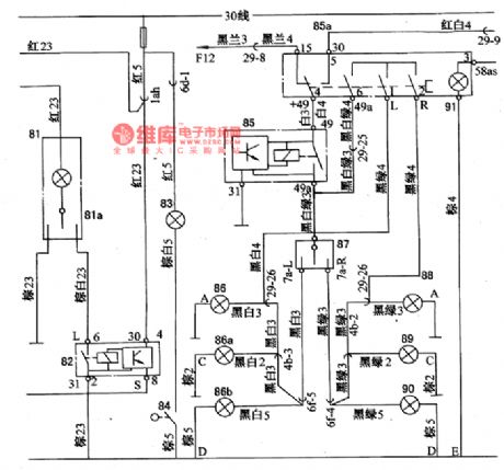
Figure: the room lamp and signal circuit of Santana 2000 (gasoline injection engine)81-the driving cab lamp; 81a-internal lamp switch; 82-internal lamp relay; 83-trunk lamp; 84-trunk contactor switch; 85-turning and danger signal flash relay; 58a-alarm signal lamp switch; 86-left turn indicator; 86a-left-head turn signal lamp; 86a-left-rear turn signal lamp; 87-turn lamp switch; 88-right turn light; 89-right-head turn light; 90-right-rear turn signal light. (View)
View full Circuit Diagram | Comments | Reading(374)
The pre-heat and indicator circuit of Nanjing Iveco light car
Published:2011/7/14 5:08:00 Author:Borg | Keyword: indicator circuit, light car
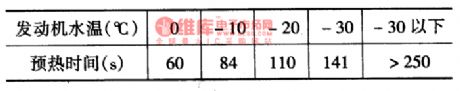
The pre-heat and indicator circuit of Nanjing Iveco light carWhen the engine water temperature is over 2℃, the system is not working. At the moment, the igniting switch is pulled to MAR gear, the pre-heat indicator 58101(with fuse mark) is only light 2S, or the indicator is put out, then the drive can start the engine. Then pull the key to the starting gear (AVV), the diesel engine is ignited immediately. If the engine water temperature is lower 2℃, the pre-heat system is working, the e-control box makes the indicator 58101 glow continuously for 35~40S, the fire injector is connected and heating. The lower the water temperature is, the longer the heating time is.
(View)
View full Circuit Diagram | Comments | Reading(868)
The instrument and indicator circuit of Nanjing Iveco light car
Published:2011/7/14 1:21:00 Author:Borg | Keyword: indicator circuit, light car
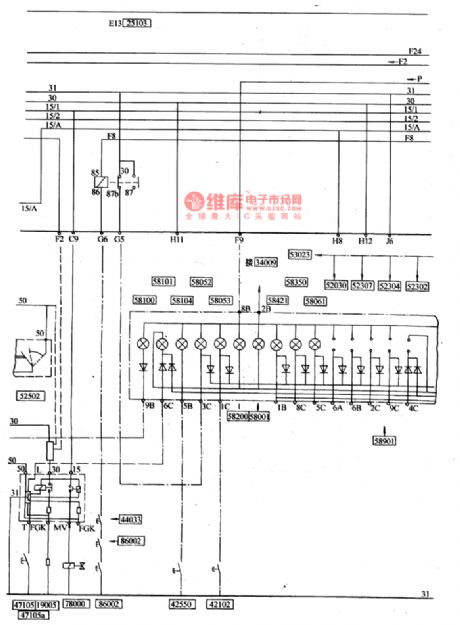
(5) indicator and instrument (see as figure 3 and 4)In the square frame of the instrument in front of the steer wheel, there are 18 parallel indicators and alarm lamps, the lamps in the upper line are (see as figure 15):1.empty; 2.fuel filter with water; 3.the air filter is blocked; 4. Pre-heat indicator; 5.engine oil pressure is too low; 6.steering indicator; 7-rear fog lamp; 8,9: vacancy. In the lower line, there are also 6 indicators: 10: vacancy; 11.ABS; 12.brake is malfunctioning, the front-end brake is broken; 13. Pulling over brake(hand brake)
(View)
View full Circuit Diagram | Comments | Reading(520)
Power Frequency Noise Filter Circuit
Published:2011/7/14 0:57:00 Author:Joyce | Keyword: Power , Frequency , Noise , Filter

As shown in the figure is a power frequency noise filter circuit. This circuit shows a kind of double T filter, which can filter out noise of 50 Hz (or60 Hz) power frequency when magnifying (such as sensors etc) weak signals . If this sort of filters constitutes of RC components only, the value of Q is generally low, and it will have attenuation characteristics like that of the broadband. Using op-amp and add positive feedback can improve the value of Q. supposing that the value of Q is Q ', then Q '= Q / (1 - K), in which, K = RA / (RA RB). Changing coefficient K would increase the value of Q. The resonance frequency of the circuit fo is 1/2 πRC,and the positive feedback components are R / 2 and 2 C. (View)
View full Circuit Diagram | Comments | Reading(1204)
Circuit of a Filter with 4 Characteristics Simultaneously
Published:2011/7/14 1:12:00 Author:Joyce | Keyword: Filter , Characteristics , Simultaneously
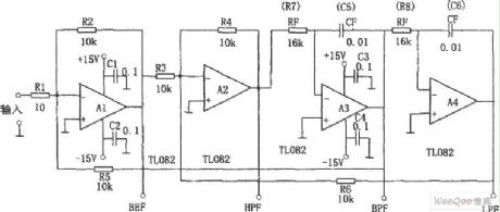
As shown in the figure is a filter circuit with four characteristics at the same time, that is band-pass (BPF), low pass (LPF), high pass (HPF) and elimination (BEF). This circuit is composed of 4 op-amps .The center frequency f0 is decided by RF and CF,as in the formula f0 = 1/2π RFCF.The value of Q in the circuit is decided by R5 / R2 ,and the gain is decided by R2 / R1. R5 = 10 k Ω, therefore when Q = 1,the output for BPF, LPF and HPF is 0 dB. When input is sine wave, output of BEF is 0, and other filters output the same voltage.
(View)
View full Circuit Diagram | Comments | Reading(484)
The illustration of the manifold meter--the pressure circuit of high and low pressure pipe
Published:2011/7/11 22:25:00 Author:Borg | Keyword: manifold meter, low pressure
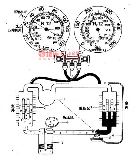
(1) cooling systemClose the 2 hand stop valve of the manifold pressure meter, connect the high pressure(red) and the low pressure(green) pipe with the according filler openings respectively, the yellow filler pipe is connected with the pump entrance, start the pump, then open the valves, when the low pressure meter indication is lower than -0.O9MPa(-740mmHg pillar), it means the pump should run for 10m more, then close the valves and keep the state for 30m, if the low pressure meter is not coming back, it mean the system has not leakage, so it can be filled with R-12, or the leakage spot should be tested.
(View)
View full Circuit Diagram | Comments | Reading(493)
| Pages:53/164 At 204142434445464748495051525354555657585960Under 20 |
Circuit Categories
power supply circuit
Amplifier Circuit
Basic Circuit
LED and Light Circuit
Sensor Circuit
Signal Processing
Electrical Equipment Circuit
Control Circuit
Remote Control Circuit
A/D-D/A Converter Circuit
Audio Circuit
Measuring and Test Circuit
Communication Circuit
Computer-Related Circuit
555 Circuit
Automotive Circuit
Repairing Circuit