
Automotive Circuit
Index 55
gain control circuit with programmable gain amplifier
Published:2011/6/12 21:37:00 Author:chopper | Keyword: gain control, programmable gain amplifier

This mode can achieve gain control by adopting the existing programmable gain amplifier integrated circuit directly.The diagram of circuitous philosophy is shown as picture 4.ICs at thisfield are PGA103,PGA204,AD526,AD620,THS7001 and so on andthe gain control only has fixed levels.Some magnifications are 1, 2, 4, 8, 16 times,and some are 1, 2, 4, 8, 16 times.The way setting the gain control are resistance setup,pin setup,and software setup.
(View)
View full Circuit Diagram | Comments | Reading(497)
Speedy Automobile Finder
Published:2011/7/9 7:40:00 Author:Felicity | Keyword: Speedy Automobile Finder
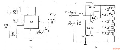
The circuit of this speedy automobile finder consists of transmitter and receiver, as showed in the figure below. The oscillating signal produced by oscillator circuit which consists of IC1, RP1, R1 and C1 transmitted by antenna W1 after being tuned by C2,L1 and C3. The wireless signal which received by W2 is frequency selected by C4, L2, C5 and amplified by IC2 to drive VL1-5. The shorter the distance between the transmitter and the receiver the stronger the signal, and the more the lighted ones of VL1-VL5. Adjusting the resistance of RP1 and RP2 can change the sensitivity of the receiver.
(View)
View full Circuit Diagram | Comments | Reading(516)
Sewage Gas Leakage Alertor
Published:2011/7/10 7:29:00 Author:Sue | Keyword: Sewage Gas, Leakage, Alertor

When there is combustible gas such as sewage gas, the gas sensor's electrode A and B will have a high resistance value. NOT GATE D1's and D3's input terminals both have low level and output terminals both have high level. VL will have green light. NOT GATE D4 outputs low level. VD is connected. The audio oscillator which consists of NOT GATE D5,D6 and R4,R5,C3 will not oscillate. HA makes no sound.
Whenthe gas sensor detectsa certain amount of sewage gas, the conducting inner resistor between A and B will become smaller which will make NOT GATE D1's and D3's input terminals have high level, and the output terminals have low level. VL will have red light. At the same time, NOT GATE D4 will output high level which will make VD disconnected. The audio oscillator will stop oscillating and will generate audio signal which will drive HA to make an alarm sound after the signal is amplified by V. (View)
View full Circuit Diagram | Comments | Reading(456)
Electronic Fish And Shrimp Catcher (2)
Published:2011/7/10 7:41:00 Author:Sue | Keyword: Electronic, Catcher
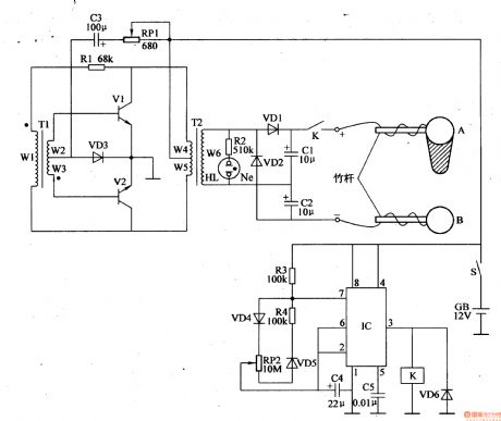
After the power switch is on, the 12v direct current voltage will provide V1 with start pulse through RP1,C3,VD3,T1 which will make V1 connected. Then under the back donation of R1,T1,T2 primary winding(W4,W5 winding), V1,V2 will go into push-pull oscillate states of intermittent connection and disconnection. T2's secondary winding(W6 winding) will generate 220v ac voltage which will become 400v direct current voltage after it is multivoltage rectificated by VD1,VD2,C1,C2, and the voltage will be put on the electrode A and B through relay K's normally open contact.
At the same time, after the astable oscillator begins to work, IC's pin 3 will output control voltage with an adjustable duty ratio which will make K work intermittently. Then between the electrode A and B there will be a continuous direct current high voltage. (View)
View full Circuit Diagram | Comments | Reading(2071)
Electronic Fish And Shrimp Catcher (1)
Published:2011/7/9 6:56:00 Author:Sue | Keyword: Electronic, Fish Catcher
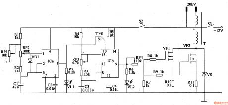
The dual time base integrated circuit IC's inner time base circuit and resistor R1,R2, capacitor C1,C2, LED VL1, potentiometer RP1,RP2 compose low frequency multivibrator. When the oscillator begins to work, VL1 will be illuminated.
IC's inner time base circuit, resistor R3,R4,LED VL2, potentiometer RP3, capacitor C3,C4 compose high frequency multivibrator. When the oscillator begins to work, VL2 will be illuminated.
The high voltage generator circuit consists of VMOS field effect transistor VF1,VF2, resistor R7-R11, zener diode VS and step-up transformer T.
Under the control oflow frequency multivibrator, the high frequency multivibrator will output pulse signal from IC's pin 9 which will generate pulse high voltage through the step-up transformer after the signal is amplified by VF1,VF2. (View)
View full Circuit Diagram | Comments | Reading(2209)
Wuling Spark meter switch, air conditioning audio circuit
Published:2011/7/10 19:29:00 Author:TaoXi | Keyword: Wuling, Spark, meter switch, air conditioning, audio circuit

The Wuling Spark meter switch, air conditioning audio circuit is as shown in the figure:
(View)
View full Circuit Diagram | Comments | Reading(838)
Hainan Mazda Familia car central door lock circuit
Published:2011/7/10 19:27:00 Author:TaoXi | Keyword: Hainan Mazda, Familia, central, door lock

The Hainan Mazda Familia car central door lock circuit is as shown in the figure:
(View)
View full Circuit Diagram | Comments | Reading(1078)
Southeast Lioncel remote control anti-theft electric door and window, cooling system, demister and heater system circuit
Published:2011/7/10 19:23:00 Author:TaoXi | Keyword: Southeast, Lioncel, remote control, anti-theft, electric door and window, cooling system, demister, heater system

The Southeast Lioncel remote control anti-theft electric door and window, cooling system, demister and heater system circuit is as shown in the figure:
(View)
View full Circuit Diagram | Comments | Reading(630)
Southeast Freeca power-supply distribution, charging, starting, ignition and cigarette lighter system circuit
Published:2011/7/10 19:08:00 Author:TaoXi | Keyword: Southeast, Freeca, power-supply distribution, charging, starting, ignition, cigarette lighter system

The Southeast Freeca power-supply distribution, charging, starting, ignition and cigarette lighter system circuit is as shown in the figure:
(View)
View full Circuit Diagram | Comments | Reading(602)
Hainan Mazda Familia sedan audio system circuit
Published:2011/7/10 19:30:00 Author:TaoXi | Keyword: Hainan, Mazda, Familia, sedan, audio system

The Hainan Mazda Familia sedan audio system circuit is as shown in the figure:
(View)
View full Circuit Diagram | Comments | Reading(623)
Southeast soveran (Mitsubishi Space) manual air conditioning circuit (6)
Published:2011/7/8 4:39:00 Author:Christina | Keyword: Southeast soveran, Mitsubishi Space, manual, air conditioning

The Southeast soveran (Mitsubishi Space) manual air conditioning circuit (6) is as shown in the figure:
(View)
View full Circuit Diagram | Comments | Reading(461)
Southeast soveran (Mitsubishi Space) manual air conditioning circuit (1)
Published:2011/7/8 4:43:00 Author:Christina | Keyword: Southeast soveran, Mitsubishi Space, manual, air conditioning

Southeast soveran (Mitsubishi Space) manual air conditioning circuit (1)
(View)
View full Circuit Diagram | Comments | Reading(539)
Southeast soveran (Mitsubishi Space) manual air conditioning circuit (2)
Published:2011/7/8 4:42:00 Author:Christina | Keyword: Southeast soveran, Mitsubishi Space, manual, air conditioning

Southeast soveran (Mitsubishi Space) manual air conditioning circuit (2)
(View)
View full Circuit Diagram | Comments | Reading(457)
Southeast soveran (Mitsubishi Space) manual air conditioning circuit (3)
Published:2011/7/8 4:41:00 Author:Christina | Keyword: Southeast soveran, Mitsubishi Space, manual, air conditioning

Southeast soveran (Mitsubishi Space) manual air conditioning circuit (3)
(View)
View full Circuit Diagram | Comments | Reading(587)
Southeast soveran (Mitsubishi Space) manual air conditioning circuit (5)
Published:2011/7/8 4:40:00 Author:Christina | Keyword: Southeast soveran, Mitsubishi Space, manual, air conditioning

Southeast soveran (Mitsubishi Space) manual air conditioning circuit (5)
(View)
View full Circuit Diagram | Comments | Reading(515)
Southeast soveran (Mitsubishi Space) manual air conditioning circuit (4)
Published:2011/7/8 4:41:00 Author:Christina | Keyword: Southeast soveran, Mitsubishi Space, manual, air conditioning

Southeast soveran (Mitsubishi Space) manual air conditioning circuit (6) is as shown in the figure:
(View)
View full Circuit Diagram | Comments | Reading(479)
BMW anti-lock braking system circuit
Published:2011/7/8 5:28:00 Author:Christina | Keyword: BMW, anti-lock braking system

View full Circuit Diagram | Comments | Reading(570)
BMW gear box circuit
Published:2011/7/8 5:27:00 Author:Christina | Keyword: BMW, gear box

View full Circuit Diagram | Comments | Reading(482)
BMW charging circuit
Published:2011/7/8 5:29:00 Author:Christina | Keyword: BMW, charging circuit

View full Circuit Diagram | Comments | Reading(546)
Automotive Fuel Monitor Three
Published:2011/7/7 9:47:00 Author:Felicity | Keyword: Automotive Fuel Monitor

While the oil level drops down, the position of the slider of RP1 goes down correspondingly to make the voltage of pin 5 of IC2 drops. The output pins output high voltage one by one and then VL1-VL10 extinguish one by one in descending order( VL10,VL9,….VL1) to indicate the oil level linearly. And the driver can know the amount of fuel directly from the LEDs which are still on.While the oil level is at its lowest (i.e. pin 1 of IC2 is high level, and VL1 is off),V1 is saturated and on to make VL11 shine. As VL11 shines, V2 periodically turns on and off to make HA send out alarm. (View)
View full Circuit Diagram | Comments | Reading(564)
| Pages:55/164 At 204142434445464748495051525354555657585960Under 20 |
Circuit Categories
power supply circuit
Amplifier Circuit
Basic Circuit
LED and Light Circuit
Sensor Circuit
Signal Processing
Electrical Equipment Circuit
Control Circuit
Remote Control Circuit
A/D-D/A Converter Circuit
Audio Circuit
Measuring and Test Circuit
Communication Circuit
Computer-Related Circuit
555 Circuit
Automotive Circuit
Repairing Circuit