Automotive Circuit
Electronic Fish And Shrimp Catcher (2)
Published:2011/7/10 7:41:00 Author:Sue | Keyword: Electronic, Catcher | From:SeekIC

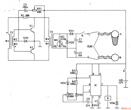
After the power switch is on, the 12v direct current voltage will provide V1 with start pulse through RP1,C3,VD3,T1 which will make V1 connected. Then under the back donation of R1,T1,T2 primary winding(W4,W5 winding), V1,V2 will go into push-pull oscillate states of intermittent connection and disconnection. T2's secondary winding(W6 winding) will generate 220v ac voltage which will become 400v direct current voltage after it is multivoltage rectificated by VD1,VD2,C1,C2, and the voltage will be put on the electrode A and B through relay K's normally open contact.
At the same time, after the astable oscillator begins to work, IC's pin 3 will output control voltage with an adjustable duty ratio which will make K work intermittently. Then between the electrode A and B there will be a continuous direct current high voltage.
Reprinted Url Of This Article:
http://www.seekic.com/circuit_diagram/Automotive_Circuit/Electronic_Fish_And_Shrimp_Catcher_2.html
Print this Page | Comments | Reading(3)

Article Categories
power supply circuit
Amplifier Circuit
Basic Circuit
LED and Light Circuit
Sensor Circuit
Signal Processing
Electrical Equipment Circuit
Control Circuit
Remote Control Circuit
A/D-D/A Converter Circuit
Audio Circuit
Measuring and Test Circuit
Communication Circuit
Computer-Related Circuit
555 Circuit
Automotive Circuit
Repairing Circuit
Code: