Automotive Circuit
Electronic Fish And Shrimp Catcher (1)
Published:2011/7/9 6:56:00 Author:Sue | Keyword: Electronic, Fish Catcher | From:SeekIC

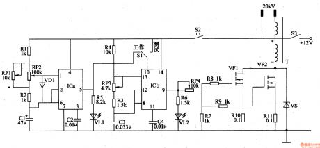
The dual time base integrated circuit IC's inner time base circuit and resistor R1,R2, capacitor C1,C2, LED VL1, potentiometer RP1,RP2 compose low frequency multivibrator. When the oscillator begins to work, VL1 will be illuminated.
IC's inner time base circuit, resistor R3,R4,LED VL2, potentiometer RP3, capacitor C3,C4 compose high frequency multivibrator. When the oscillator begins to work, VL2 will be illuminated.
The high voltage generator circuit consists of VMOS field effect transistor VF1,VF2, resistor R7-R11, zener diode VS and step-up transformer T.
Under the control oflow frequency multivibrator, the high frequency multivibrator will output pulse signal from IC's pin 9 which will generate pulse high voltage through the step-up transformer after the signal is amplified by VF1,VF2.
Reprinted Url Of This Article:
http://www.seekic.com/circuit_diagram/Automotive_Circuit/Electronic_Fish_And_Shrimp_Catcher_1.html
Print this Page | Comments | Reading(3)

Article Categories
power supply circuit
Amplifier Circuit
Basic Circuit
LED and Light Circuit
Sensor Circuit
Signal Processing
Electrical Equipment Circuit
Control Circuit
Remote Control Circuit
A/D-D/A Converter Circuit
Audio Circuit
Measuring and Test Circuit
Communication Circuit
Computer-Related Circuit
555 Circuit
Automotive Circuit
Repairing Circuit
Code: