Automotive Circuit
Index 49
Single precision function generator ICL8038 application circuit (b)
Published:2011/7/18 6:06:00 Author:John | Keyword: Single precision function generator, application circuit
View full Circuit Diagram | Comments | Reading(865)
Single precision function generator ICL8038 application circuit (c)
Published:2011/7/18 6:07:00 Author:John | Keyword: Single precision function generator, application circuit
View full Circuit Diagram | Comments | Reading(2587)
NE566V generated sawtooth circuit
Published:2011/7/18 19:27:00 Author:John | Keyword: sawtooth, NE566V
View full Circuit Diagram | Comments | Reading(452)
Servo position remote control circuit
Published:2011/7/12 10:28:00 Author:John | Keyword: remote control, Servo

Servo position remote control circuit is shown. The system includes three components, which are named the square wave generator, servo amplifier and servo. Appropriate square wave is added to input end of the amplifier through wires. The position’s regulation potentiometer of the square wave generator can decide the servo motor’s position.
(View)
View full Circuit Diagram | Comments | Reading(565)
three-phase motor phase-shifting starter
Published:2011/7/15 21:05:00 Author:chopper | Keyword: phase-shifting starter

Three-phase AC motor usually requires to install phase-shifting capacitor to start when it uses 220V voltage.As for the three-phase AC motor whose power is 2-3KW,it needs the phase-shifting capacitor whose capacity is over 2OOμF,and the capacitor size is bigger,the price is higher.This example describes the three-phase motor phase-shifting starter,which can replace the phase-shifting capacitor,and make the three-phase AC motor in 220V AC supply voltage easier to start, and more reliable than phase-shifting capacitor.
(View)
View full Circuit Diagram | Comments | Reading(591)
substitutive motor centrifugal switch circuit(2)
Published:2011/7/16 20:04:00 Author:chopper | Keyword: centrifugal switch

The principle of circuit The substitutive motor centrifugal switch circuit is formed by the capacitors C1,C2,resistor R,the relay K, the diodes VD1,VD2 and thermal relay KR,which is shown in Figure 4-126. After the power supply is turned on,one of the 220V AC voltage is added to the main winding of motor M(W1) through thermal relay KR,and the other is added to the starter circuit composed of the capacitor C3 and secondary winding (W2) of motor Mthrough normal closed contact of relay K,and then the motor M will start.
(View)
View full Circuit Diagram | Comments | Reading(2032)
substitutive motor centrifugal switch circuit
Published:2011/7/16 19:55:00 Author:chopper | Keyword: centrifugal switch

The principle of circuit The substitutive motor centrifugal switch circuit is formed by the power supply circuit and delay control circuit,which is shown in Figure 4-125. The power supply circuit is formed by the capacitor C1,discharge resistor R1,rectifier diodes VD1,VD2,filter capacitor C2 and voltage-regulator diode VS. Delay control circuit is formed by the resistor,capacitor C3,diodes VD3,VD4,transistors V1,V2,and the relay K. 20V AC voltage is dropped by C1,rectifiered by VD1 and VD2,filtered by C2 and regulated by VS,and then offer the delay circuit +12V operating power supply.
(View)
View full Circuit Diagram | Comments | Reading(3396)
Audi A6-Mobile phone adapter device circuit Figure 2
Published:2011/7/15 2:33:00 Author:Fiona | Keyword: Mobile phone adapter device
View full Circuit Diagram | Comments | Reading(385)
Audi A6-Mobile phone adapter device circuit Figure 1
Published:2011/7/15 2:34:00 Author:Fiona | Keyword: Mobile phone adapter device
View full Circuit Diagram | Comments | Reading(371)
Audi A6-Mobile phone adapter device circuit
Published:2011/7/15 2:34:00 Author:Fiona | Keyword: Mobile phone adapter device
View full Circuit Diagram | Comments | Reading(468)
Audi A6-Electronic parking and hand brake circuit Figure 2
Published:2011/7/15 2:36:00 Author:Fiona | Keyword: Electronic parking, hand brake
View full Circuit Diagram | Comments | Reading(1163)
Audi A6-Electronic parking and hand brake circuit Figure 1
Published:2011/7/15 2:37:00 Author:Fiona | Keyword: Electronic parking, hand brake
View full Circuit Diagram | Comments | Reading(1846)
High-power electronics insect expelling device circuit
Published:2011/7/15 2:40:00 Author:Fiona | Keyword: electronics insect expelling device

High-power electronics insect expelling device circuit is shown sa above:
(View)
View full Circuit Diagram | Comments | Reading(424)
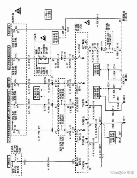
Shanghai Buick engine control part circuit
Published:2011/7/16 8:06:00 Author:Fiona | Keyword: engine control

Shanghai Buick engine control part circuit is shown as above:
(View)
View full Circuit Diagram | Comments | Reading(357)
Homemade 12 V vehicle interior lighting LED circuit
Published:2011/7/16 8:13:00 Author:Fiona | Keyword: vehicle interior, lighting LED

Homemade 12 V vehicle interior lighting LED circuit is showen as above:
(View)
View full Circuit Diagram | Comments | Reading(435)
Wireless remote control add, subtract resistor network circuit
Published:2011/7/16 8:53:00 Author:Fiona | Keyword: Wireless remote control, add, subtract resistor

Wireless remote control add, subtract resistor network circuit is shown as above:
(View)
View full Circuit Diagram | Comments | Reading(526)
Maverick 2005 electric seats circuit
Published:2011/7/15 2:03:00 Author:Fiona | Keyword: electric seats
View full Circuit Diagram | Comments | Reading(416)
maverick 2005 electrothermal windows circuit
Published:2011/7/15 2:15:00 Author:Fiona | Keyword: electrothermal windows
View full Circuit Diagram | Comments | Reading(410)
maverick 2005 supplemental restraint system circuit
Published:2011/7/15 2:16:00 Author:Fiona | Keyword: supplemental restraint system
View full Circuit Diagram | Comments | Reading(429)
maverick 2005 rear wiper and scrubber circuit
Published:2011/7/15 2:17:00 Author:Fiona | Keyword: rear wiper, scrubber
View full Circuit Diagram | Comments | Reading(460)
| Pages:49/164 At 204142434445464748495051525354555657585960Under 20 |
Circuit Categories
power supply circuit
Amplifier Circuit
Basic Circuit
LED and Light Circuit
Sensor Circuit
Signal Processing
Electrical Equipment Circuit
Control Circuit
Remote Control Circuit
A/D-D/A Converter Circuit
Audio Circuit
Measuring and Test Circuit
Communication Circuit
Computer-Related Circuit
555 Circuit
Automotive Circuit
Repairing Circuit


