
Automotive Circuit
Index 54
The Shanghai air-conditioning system circuit in Nanjing Iveco A40.10 light car
Published:2011/7/12 0:36:00 Author:Borg | Keyword: air-conditioning system, Nanjing Iveco
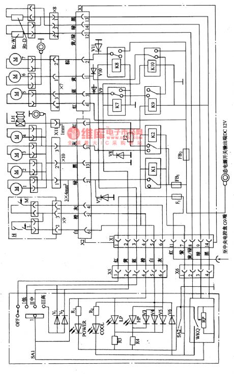

(6) The Shanghai air-conditioning system circuit in Nanjing Iveco A40.10 light car In the KQZN101 air-conditioning system of A40.10 light car (see as figure 26), there are 4 axis flowing condensers, which are M1, M2, M3 and M4, 3 evaporators of M5, M6 and M7 (2-axis centrifugal), there is also the wind switch SA1 on the dashboard, LED indicator, alarm lamp, temperature switch WKQ and hand control switch SA2. To read it more conveniently, figure 26 is simplified as figure 27. When the switch SA1 is closed, the temperature controller WKQ is getting into working.
(View)
View full Circuit Diagram | Comments | Reading(536)
The Shanghai air-conditioning system circuit of Nanjing Iveco A40.10 light car (middle-roof)
Published:2011/7/12 0:48:00 Author:Borg | Keyword: air-conditioning system, light car
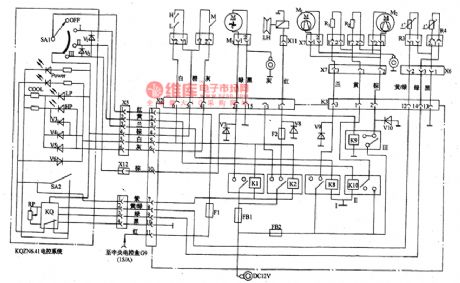
(5)The Shanghai air-conditioning system circuit of Nanjing Iveco A40.10 light car (middle-roof) (see as figure 25)The car is controlled by the KQSN6-4Ⅰelectric control system. On the dashboard, there is the wind volume switch SA1, temperature switches KQ and SA2, power supply indicator POWER cooling indicator COOL, the high voltage indicator HP and lower voltage fault indicator LP. The wind volume switch power is from the connection terminal G9 in the central box of the car, which is under the control of 15/A pillar, and the power supply of other motors andcompressors is the battery positive pole (DC12V) which connects with all the contactor of all the relays.
(View)
View full Circuit Diagram | Comments | Reading(1274)
the circuit of the granary full reminder for the combine harvester (2)
Published:2011/7/8 7:34:00 Author:Ariel Wang | Keyword: granary full , reminder, combine harvester

When the granary is not full,the resistence of RC is low as it is irradiated by extraneous light.V1 is conducted.V2 is stopped.K is released.H1-2 aren't lighted.When the granary is full,the food shelters RC.the resistence of RC is large as it isn't irradiated by light.V1 is stopped.V2 is conducted.K is pulled in.The normally open contactors are connected.HL2 is lighted.HA gives out alarm sound.It informs the driver the granary is full. When at night,you should connect 51 as the extraneous light is too dim.Then HL1 is lighted.It prevents the alarm device from malfunction.
(View)
View full Circuit Diagram | Comments | Reading(434)
the fill light circuit of the chicken farm(2)
Published:2011/7/8 5:22:00 Author:Ariel Wang | Keyword: fill light, chicken farm

The 220V AC voltage is reduced by T,commutated by VD1~VD4,filtered by C2 and regulated IC.Then it becomes +9V voltage.It is the working power supply for the photometry circuit and the dimming circuit.At the same time,VL is lighted by R4.When in the daytime,the resistence of RC is low.V1~V3,VU and VT are stopped.EL isn't lighted.When in the cloudy and rainy day,the resistence of RC increases.V1~V3,VU and VT are all conducted.EL is lighted.The dimmer the light,the stronger the electric current,the faster of the C1's charging speed.The trigger pulse generated by VU increases the conduction angle of VT.And the brightness of EL becomes stronger.
(View)
View full Circuit Diagram | Comments | Reading(461)
the alarm circuit of the blocked seed channel in seeding-machine (1)
Published:2011/7/7 6:43:00 Author:Ariel Wang | Keyword: alarm , blocked , seed channel , seeding-machine

VL and VD are relatively set in the transmit seed tube.The infrared light which is emitted by V2 shines on VD.When seeding,if the transmit seed tube of the seeding-machine works right.The infrared light is sheltered by the seeds every now and then.The base electrode of V1 will generate a series continuous negtive pulse.V1 is conducted at a interval time.The pin-2 and pin-6 output low level.The pin-3 outputs high level.V2 is saturated to conduct.The audio oscillator consists of Y3,Y4,C5 and R7 stops oscillation.B1 doesn't give a sound.You can adjust the resistence of RP.It can change the action sensibility of the the trigger circuit. (View)
View full Circuit Diagram | Comments | Reading(442)
the controller circuit of the temperature(10)
Published:2011/7/7 6:51:00 Author:Ariel Wang | Keyword: controller, temperature

The 220V AC voltage is reduced by T,commutated by VD1~VD4,regulated by IC5,filtered by C1.It provides +9V working voltage for the temperature indicator circuit of LED and the control circuit of the heater.IC1 is the voltage-type positive temperature coefficient integrated temperature sensor.The sensibility is 10mV/℃.The output voltage is 2.73V when it's 0℃.The output voltage is 3.73V when it's 100℃.When the detected temperature changes,the output voltage of IC1 and the input voltage from the pin-5 of IC4 change synchronously. When it's processed by tenth voltage comparator in IC4,the drivers VL1~VL10 give out the light.It indicates the temperature value.
(View)
View full Circuit Diagram | Comments | Reading(465)
the alarm circuit for blocked fertilization tube of the seeding-machine
Published:2011/7/7 6:40:00 Author:Ariel Wang | Keyword: blocked, fertilization tube , seeding-machine

When you plant the crops and fertilize them,the liquid fertilizer in the fertilization storage tank goes to the ditching tube through the metal tube 2 and the metal tube 4.Then it goes to the soil.When the tube is unclogged,there is no liquid fertilizer in the metal tube 1.If there is liquid fertilizer in the metal tube 2 and 4,B and C is connected by the resistence of the liquid fertilizer.V1 and V2 are conducted.V3 is stopped.There are no liquid fertilizer in the metal tube 1 .It is insulated between A and B.So it is open-circuit between A and B.V4 and Y4 are stopped.K is released.HL is not lighted.HA doesn't give a sound. (View)
View full Circuit Diagram | Comments | Reading(460)
the circuit of the temperature controller(14)
Published:2011/6/28 8:11:00 Author:Ariel Wang | Keyword: temperature controller

RP is used to set the middle temperature.RT is used to detect the environment temperature.When the environment temperature is lower than the temperature set by RP,the resistence of RT increases.The pin-2 of IC1 outputs high level.Pin-12 and pin-11 output low level.VL2 and VL1 are lighted.It indicates the environment temperature is at a low level.At the same time,V1 is conducted.The relay K1 is conducted to pull in.The normally open contact is connected.The electric heater EH is conducted to work.It starts to heat.When the environment temperature rises to the temperature set by RP,the pin-11 of IC2 outputs high level.VL1 dies out.V1 is stopped.K1 is released.EH stops heating.At the same time,the pin-12 of IC1 outputs low level.VL2 is lighted.It indicates the environment temperature is the set temperature.
(View)
View full Circuit Diagram | Comments | Reading(390)
the circuit of the multifunctional protector for electric motor(1)
Published:2011/6/28 8:11:00 Author:Ariel Wang | Keyword: multifunctional protector , electric motor

When 51 is pressed,the AC contactor KM is conducted to pull in.Three pairs of normally open contacts are connected.The electric motor M works.The AC voltage of L2 and L3 is reduced by C1,commutated by VD1~VD4,current limited by R3,regulated by VS1 and filtered by C2.Then it generates +12V voltage.It is for the control & protection circuit.At the same time,V1 is lighted.The +12V voltage is branched by R13 and R12.It provides reference voltage for inverting input ends of N1~N3 and non-inverting end of N4.TAI~TA3 are used to detect the two-phase power supply line of electric motor.And it generates 3 voltage signals for detect at R14~R16.
(View)
View full Circuit Diagram | Comments | Reading(445)
the circuit of the humidity controller(1)
Published:2011/7/7 6:28:00 Author:Ariel Wang | Keyword: humidity , controller

One part of the 220V AC voltage is reduced by T,commutated by UR,filtered by C1 and regulated by IC1.Then it generates +12V voltage for the humidity control circuit.At the same time,VL is lighted.The other part is reduced by T,current limitted by RI,regulated and clipped by VS2.Then it becomes flat-top AC voltage G.It is adjusted and sampled by RP1,reduced by RS and commutated by VD1~VD4.Then it becomes DC voltage.It is filted and current limitted by C2,R3 and CZ.Then it goes to the ammeter PA.The resistence of RS changes when the humidity changes.The environment humidty is higher,the resistence of ItS is lower.And the DC current passing through PA is larger.
(View)
View full Circuit Diagram | Comments | Reading(1408)
the circuit of the multifunctional protector for electric motor(4)
Published:2011/7/7 6:28:00 Author:Ariel Wang | Keyword: multifunctional protector, electric motor

the working principle of the circuitSee as the chart above.The input voltage detecting circuit consists of the resistors RI~R3 and the varistors RV1~RV3.It is the balanced three phase circuit .When the three phase AC power supply is normal,the potential of the common point(A point) is 0V.When any phase of voltage in three phase AC power supply is abnormal(the voltage is too high or phase failure),the potencial of the common point rises.It conducts the in-circuit of the solid state relay KN.The coil in AC contactor KM is short-circuit.KM is released.It cuts off the input voltage.So it protects the electric motor. (View)
View full Circuit Diagram | Comments | Reading(408)
the circuit of the double hresholds temperature alertor(1)
Published:2011/7/7 6:49:00 Author:Ariel Wang | Keyword: double hresholds, temperature, alertor

When the temperature is beyond the upper limit of the set temperature,the temperature of RT is decreased.The neutral pointpotential of RP1 is increased.D1 outputs low level.V1 is conducted.VL1 is lighted.It indicates the temperature beyond the upper limit.At the same time,VD1 is stopped.The 1Hz low-frequency oscillator and the 1kHz audiofrequency oscillator start to work.The 1Hz low-frequency oscillator modulates the 1kHz audiofrequency oscillator.HA gives out alam sound every now and then.When the temperature is lower than the lower limit of the set temperature,the resistence of RT is increased.The neutral point potential of RP2 is decreased.D2 outputs high level.1/2 is conducted.VL2 is lighted.It indicates the temperature is lower than the lower limit.At the same time,the 1Hz low-frequency oscillator and the 1kHz audiofrequency oscillator starts to work.HA give out alarm sound. (View)
View full Circuit Diagram | Comments | Reading(399)
the control circuit of electric fence part 6
Published:2011/6/13 7:04:00 Author:Ariel Wang | Keyword: control, electric, fence

The impulsed voltage output circuit is composed by NAND gate in IC,field effect transistor VF and pulse transformer T.When the mains switch S gets through,the oscillator works.NAND gate D2 outputs oscillatory signal .It is buffered and processed by NAND gate D3 .Then it goes to the grid of VF.It conducts VE at interval time.It will generate about 200V impulsed voltage.It goes to the electric fence.It gives animals deterrence .You can adjust the resistence of RP,in order to change the working frequency of the oscillator.
(View)
View full Circuit Diagram | Comments | Reading(996)
Availability of IP / decimal output conversion circuit
Published:2011/7/8 3:21:00 Author:Fiona | Keyword: IP / decimal output

Circuit Work
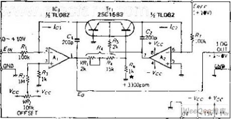
As we all know,there exists logarithmic relationship between the transistor base very- occurs very voltage VBM and the collector current IO. Using this relationship can be made the log conversion circuit, the circuit principle expressed by the following relationship: IO1 and IO2 ratio is converted to logarithms, partial pressure ratio determines the constants,in order to make the change 10 times to obtain 1V output, according to [(R5 + R4) / R6] * 60 = 1000MV,it can get partial pressure ratio, the ratio value is 16.7. If R6 = 1K, then R4 = 15.7K, It adds ★ mark where the resistance is 1K at the circuit diagram, which means that in order to do the temperature compensation for transistor VBE, the resistance is thermistor which has a +3300 PPM / ℃ temperature characteristic. IC1 is the input current used for converting, reference current IC2 is supplied by the OP amplifier A2. (View)
View full Circuit Diagram | Comments | Reading(443)
ABS Circuit One of Southeast LingShuai Cars
Published:2011/7/7 21:09:00 Author:Michel | Keyword: LingShuai Cars, ABS Circuit One
View full Circuit Diagram | Comments | Reading(389)
ABS Circuit Two of Southeast LingShuai Cars
Published:2011/7/7 21:11:00 Author:Michel | Keyword: LingShuai Cars, ABS Circuit Two

ABS Circuit of Southeast LingShuai Cars (View)
View full Circuit Diagram | Comments | Reading(379)
ABS Circuit Three of Southeast LingShuai Cars
Published:2011/7/7 21:12:00 Author:Michel | Keyword: LingShuai Cars, ABS Circuit Three
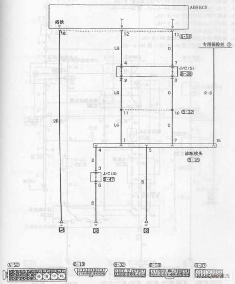
ABS Circuit of Southeast LingShuai Cars (View)
View full Circuit Diagram | Comments | Reading(385)
The Bora phone electric control unit, aerial, microphone circuit
Published:2011/7/10 10:44:00 Author:Seven | Keyword: Bora, electric control unit, microphone
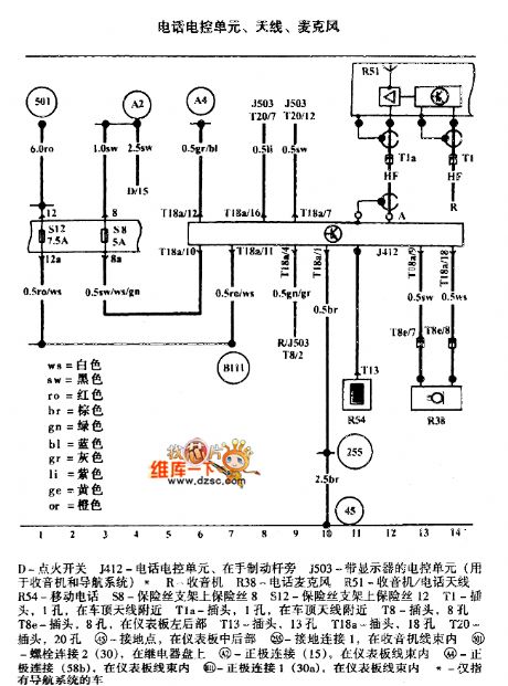
The Bora phone electric control unit, aerial, microphone circuit is shown as above.
D-igniting switch J412-phone control unit, at the side of the brake J503-the control unit with the display(used in radios and guided system) R-radio R38-phone microphone R51-radio/phone aerial R54-cell phone S8-fuse on the holder 8 S12-fuse on the holder 12 T1-plug, 1 hole, near the car ceiling aerial T1a-plug, 1 hole, near the car ceiling aerial T8-plug, 8 holes T8e-plug, 8 holes, in the rear part of the instrument T13-plug, 13 holes T18a-plug, 18 holes T20-plug, 20 holes (View)
View full Circuit Diagram | Comments | Reading(652)
BMW7 series 740i E38DWA IV anti-theft system circuit (2)
Published:2011/7/8 5:50:00 Author:Christina | Keyword: BMW7 series, 740i, anti-theft system

BMW7 series 740i E38DWA IV anti-theft system circuit (2)
(View)
View full Circuit Diagram | Comments | Reading(362)
economic light of voltage reduced capacitance circuit
Published:2011/6/28 3:13:00 Author:chopper | Keyword: economic light, voltage reduced capacitance
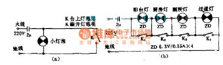
This circuit is simple but practical.For example:(a)When K is close,impact current will be shorted by K,and bulb will go out.When K is open,the bulb will light.The control method of K is opposite to the normal method.(b)This picture describes several small bulbs in seriesfor lighting use.The capacitance is used to compensate power,and eliminate the outside interference.When we use this circuit,we must be careful and pay more attention.
(View)
View full Circuit Diagram | Comments | Reading(425)
| Pages:54/164 At 204142434445464748495051525354555657585960Under 20 |
Circuit Categories
power supply circuit
Amplifier Circuit
Basic Circuit
LED and Light Circuit
Sensor Circuit
Signal Processing
Electrical Equipment Circuit
Control Circuit
Remote Control Circuit
A/D-D/A Converter Circuit
Audio Circuit
Measuring and Test Circuit
Communication Circuit
Computer-Related Circuit
555 Circuit
Automotive Circuit
Repairing Circuit