Automotive Circuit
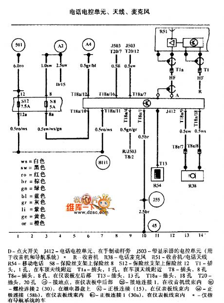
The Bora phone electric control unit, aerial, microphone circuit
Published:2011/7/10 10:44:00 Author:Seven | Keyword: Bora, electric control unit, microphone | From:SeekIC

The Bora phone electric control unit, aerial, microphone circuit is shown as above.
D-igniting switch J412-phone control unit, at the side of the brake J503-the control unit with the display(used in radios and guided system) R-radio R38-phone microphone R51-radio/phone aerial R54-cell phone S8-fuse on the holder 8 S12-fuse on the holder 12 T1-plug, 1 hole, near the car ceiling aerial T1a-plug, 1 hole, near the car ceiling aerial T8-plug, 8 holes T8e-plug, 8 holes, in the rear part of the instrument T13-plug, 13 holes T18a-plug, 18 holes T20-plug, 20 holes
Reprinted Url Of This Article:
http://www.seekic.com/circuit_diagram/Automotive_Circuit/The_Bora_phone_electric_control_unit_aerial_microphone_circuit.html
Print this Page | Comments | Reading(3)

Article Categories
power supply circuit
Amplifier Circuit
Basic Circuit
LED and Light Circuit
Sensor Circuit
Signal Processing
Electrical Equipment Circuit
Control Circuit
Remote Control Circuit
A/D-D/A Converter Circuit
Audio Circuit
Measuring and Test Circuit
Communication Circuit
Computer-Related Circuit
555 Circuit
Automotive Circuit
Repairing Circuit
Code: