Automotive Circuit
Golf Bora Radio Circuit
Published:2011/7/26 9:54:00 Author:Robert | Keyword: Golf, Bora, Radio | From:SeekIC


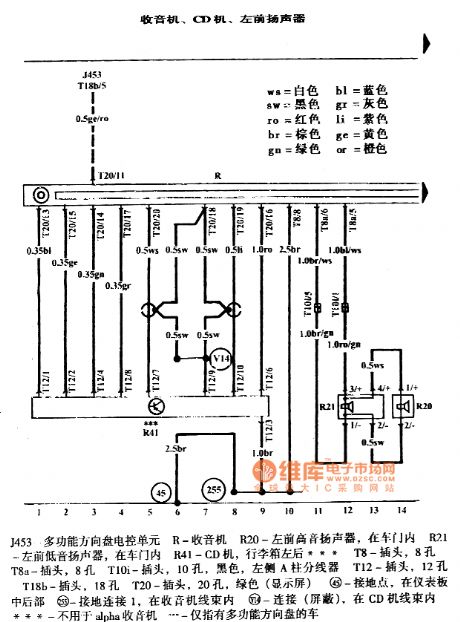
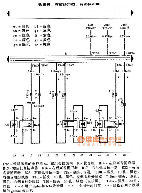
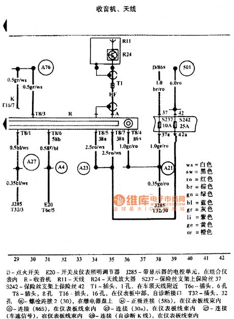
The pictures show the Golf Bora radio circuits.
The first picture shows the radio, CD player, left-front speaker.
The second picture shows the radio, right-front speaker, rear speaker.
The third picture shows the radio and antenna. In the picture the part D is ignition switch. The E20 is switch and instrument lighting regulator. The J285 is an ECU with monitor inside the instrument cluster. The R is radio. The R11 is antenna. The R24 is antenna amplifier. The S237 is the fuse on the fuse holder 37. The S242 is the fuse on the fuse holder 42. The T1 is a plug with 1 hole near the car roof antenna. The T6c is plug with 6 holes. The T8 is plug with 8 holes. The T16 is plug at the middle of the dashboard with the self-diagnosis interface. The T32 is plug with 32 holes. And so on.
Reprinted Url Of This Article:
http://www.seekic.com/circuit_diagram/Automotive_Circuit/Golf_Bora_Radio_Circuit.html
Print this Page | Comments | Reading(3)

Article Categories
power supply circuit
Amplifier Circuit
Basic Circuit
LED and Light Circuit
Sensor Circuit
Signal Processing
Electrical Equipment Circuit
Control Circuit
Remote Control Circuit
A/D-D/A Converter Circuit
Audio Circuit
Measuring and Test Circuit
Communication Circuit
Computer-Related Circuit
555 Circuit
Automotive Circuit
Repairing Circuit
Code: