Automotive Circuit
Automotive Fuel Monitor Five
Published:2011/7/17 5:56:00 Author:Felicity | Keyword: Automotive Fuel Monitor | From:SeekIC


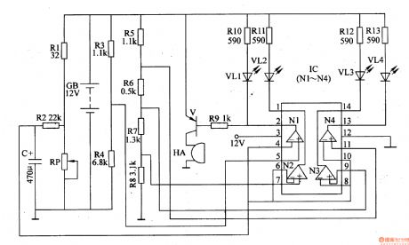
The circuit consists of oil level monitoring circuit, the oil level indicating circuit and lacking fuel alarm circuit.
Oil level monitoring circuit consists of automotive fuel tank float potentiometer RP, resistors Rl, R2 and capacitor C.
The oil level indicating circuit consists of R3-R8, RlO-R13, LED VL1-VL4 and quad op amp IC IC (Nl-N4).
Lacking fuel alarm circuit consists of resistor R9, transistor V and buzzer HA.
The voltage divider circuit consist of R3-R8 and the circuit provides standard oil level voltage for the non-inverting terminal of N1-N4 inside IC; The voltage divided by R1 and RP and then put on to inverting terminal of N1-N4 through R2 as the oil amount sample voltage.
When the fuel tank is full of oil, the resistance of RP is at its lowest and N1, N3, N4 output high level voltage, VL2 output low level voltage. And the yellow LED VL2 is on indicating the fuel tank is full.
When the tank is 3/4 full, N3 also output low level voltage to make green led VL3 on.
When the tank is 1/2 full, N4 also output low level voltage to make green led VL4 on.
When the tank is 1/4 full, N1 also output low level voltage to make red led VL1 and V on. And the beeper beeps to remind the driver to refuel.
Reprinted Url Of This Article:
http://www.seekic.com/circuit_diagram/Automotive_Circuit/Automotive_Fuel_Monitor_Five.html
Print this Page | Comments | Reading(3)

Article Categories
power supply circuit
Amplifier Circuit
Basic Circuit
LED and Light Circuit
Sensor Circuit
Signal Processing
Electrical Equipment Circuit
Control Circuit
Remote Control Circuit
A/D-D/A Converter Circuit
Audio Circuit
Measuring and Test Circuit
Communication Circuit
Computer-Related Circuit
555 Circuit
Automotive Circuit
Repairing Circuit
Code: