Automotive Circuit
Power Line Carrier Remote Alarm Circuit
Published:2011/7/20 3:09:00 Author:Joyce | Keyword: Power Line , Carrier, Remote Alarm | From:SeekIC


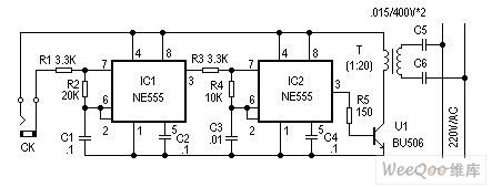
The alarm introduced here does not need circumscribed circuit, but an electric power circuit to send warning signs. Alarm points can be set in many places to conduct sound and light alarm warning for an emergency. It can be used extensively.
Working principle:
This alarm is composed of sending and receiving signals .The principle of the reflection circuit is as shown in figure 1. It shows two oscillating circuits with different frequency formed by the two 555 time base circuits. When two ends of CK form a short circuit (short circuit alarm probe signal), the first piece (IC1) 555 constitutes a low frequency oscillation circuit, and frequency F1 is mainly decided by C1, R2, and output frequency of feet 3 is the low frequency signal of F1.When feet 3 of IC1 outputs high levels , the second piece IC2 (555) constitutes a high frequency oscillation circuit, and the oscillation frequency is mainly decided by C3, R4.
Components selection and circuit adjustment:

Reprinted Url Of This Article:
http://www.seekic.com/circuit_diagram/Automotive_Circuit/Power_Line_Carrier_Remote_Alarm_Circuit.html
Print this Page | Comments | Reading(3)

Article Categories
power supply circuit
Amplifier Circuit
Basic Circuit
LED and Light Circuit
Sensor Circuit
Signal Processing
Electrical Equipment Circuit
Control Circuit
Remote Control Circuit
A/D-D/A Converter Circuit
Audio Circuit
Measuring and Test Circuit
Communication Circuit
Computer-Related Circuit
555 Circuit
Automotive Circuit
Repairing Circuit
Code: