
Automotive Circuit
Index 64
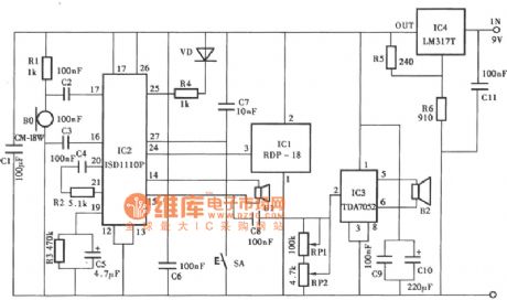
Electronic guard dog circuit
Published:2011/6/28 21:50:00 Author:chopper | Keyword: Electronic, guard dog
View full Circuit Diagram | Comments | Reading(621)
Motor Phase Failure Protector (5)
Published:2011/6/28 7:02:00 Author:Sue | Keyword: Motor, Phase Failure, Protector
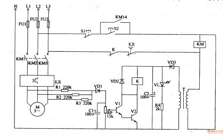
When S2 is pushed, the voltage between L2 and L3 will be put on KM through S1,S2,K,KR. KM will be connected. M begins to work. The other circuit will provide the drive circuit with 12V working voltage. At the same time, VL is illuminated.
When the three phases work well, V1 V2 are disconnected and K is released.
When there is phase failure, there will be a voltage between VD1 and N, which will make V1 V2 are connected after filtration and rectification. K is connected and KM is released. M's working power is cut off. (View)
View full Circuit Diagram | Comments | Reading(585)
Motor Phase Failure Protector (4)
Published:2011/6/28 6:55:00 Author:Sue | Keyword: Motor, Phase Failure, Protector
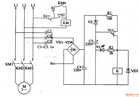
When the power works well,A has a low voltage and the voltage is not enough to make VS VU connected. K is not connected and M keeps working.
When there is phase failure, 12V voltage will be generated between A and N. The voltage will make VS connected. C5 begins to be charged. VU is connected and VL is illuminated. K is connected. KM is released and M's working power is cut off.
When the power returns to normal, VU is disconnected and K is released. When S2 is pushed the motor will start to work again. (View)
View full Circuit Diagram | Comments | Reading(1487)
Motor Phase Failure Protector (3)
Published:2011/6/28 6:50:00 Author:Sue | Keyword: Motor, Phase Failure, Protector
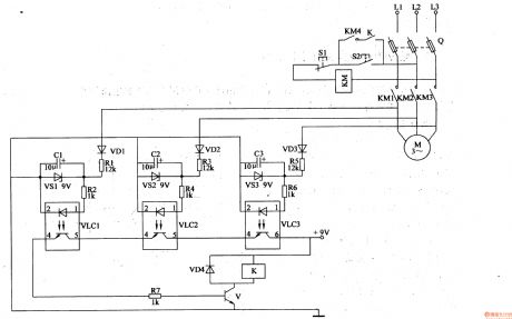
When S2 is pushed, KM is connected and KM1-KM4 are connected. M begins to work. LEDs in VLC1-VLC3 are illuminated. V is connected and K is connected. When S2 is released, KM keeps connected.
When there is phase failure, V is disconnected and K is disconnected. When S2 is released, KM is released and this will protect the circuit. (View)
View full Circuit Diagram | Comments | Reading(1514)
Motor Phase Failure Protector (2)
Published:2011/6/28 6:46:00 Author:Sue | Keyword: Motor, Phase Failure, Protector

When S2 is pushed, K is connected. When S2 is released, M keeps working.
When phase L1,L2 fail, TA will generate signal voltage and makes V1 connected. V3 is disconnected. K is released. KM is released. M's working power is cut off.
When phase L3 fails, TA has no voltage and V3 V2 are disconnected. M stops working. (View)
View full Circuit Diagram | Comments | Reading(730)
Motor Phase Failure Protector (1)
Published:2011/6/28 6:40:00 Author:Sue | Keyword: Motor, Phase Failure, Protector
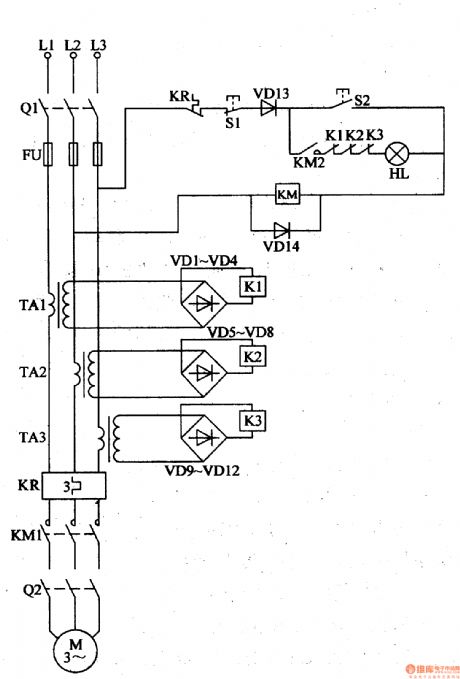
When Q1 is connected and S2 is pushed, KM begins to work. KM KM2 are connected. If Q2 is connected, M will begin to work.
When M begins to work, TA1-TA3 will generate 6V voltage. K1-K3 begin to work and K1-K3 are connected. When S2 is released, KM remains connected. HL is illuminated and the motor keeps working.
When there is phase failure, KM is disconnected and M's power is cut off. (View)
View full Circuit Diagram | Comments | Reading(452)
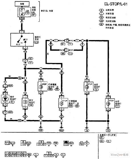
Nissan A32-EL brake lamp circuit
Published:2011/6/22 10:00:00 Author:Nancy | Keyword: Nissan, brake lamp
View full Circuit Diagram | Comments | Reading(538)
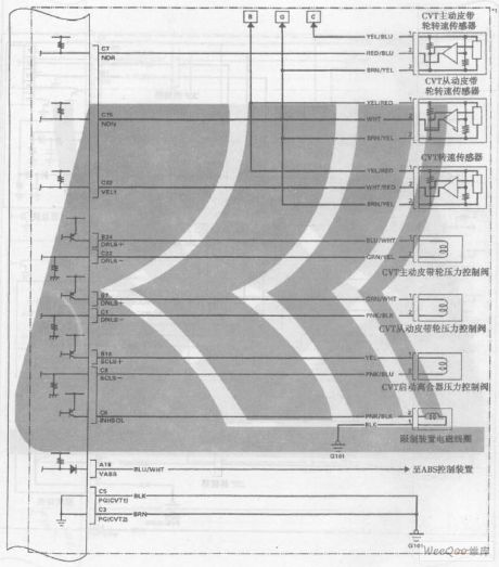
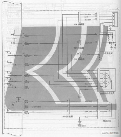
GuangZhou HONDA Fit saloon car 6-speed CVT + 7-speed mode circuit 2
Published:2011/6/19 19:08:00 Author:TaoXi | Keyword: GuangZhou, HONDA, Fit, saloon car, 6-speed, CVT, 7-speed mode
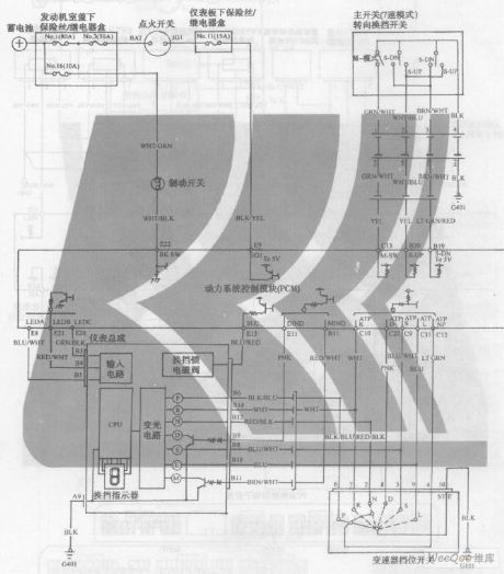
GuangZhou HONDA Fit saloon car 6-speed CVT + 7-speed mode circuit (View)
View full Circuit Diagram | Comments | Reading(391)
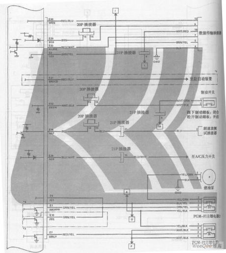
GuangZhou HONDA Fit saloon car 6-speed CVT + 7-speed mode circuit 1
Published:2011/6/19 19:07:00 Author:TaoXi | Keyword: GuangZhou, HONDA, Fit, saloon car, 6-speed, CVT, 7-speed mode
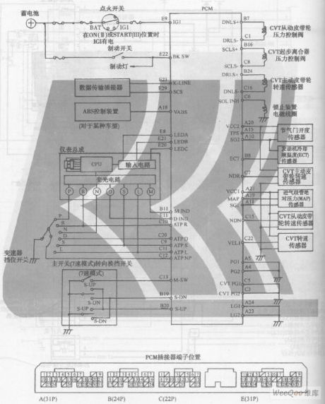
GuangZhou HONDA Fit saloon car 6-speed CVT + 7-speed mode circuit (View)
View full Circuit Diagram | Comments | Reading(450)
The oscillating circuit with the output of sine and square waves(LM111 and LM101A)
Published:2011/6/14 2:08:00 Author:Borg | Keyword: oscillating circuit, sine and square waves
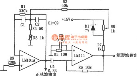
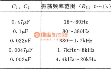
In ordinary RC oscillating circuits, if we want a wide frequency changing range, we not only need to change the resistor, but also need to change the capacitor. However, this circuit only needs a resistor R3 to do this. In the figure, the computing amplifier LM101A forms a band-pass filter, LM111 is a LEV comparator which forms a amplitude limiter. Because of the forward and backward feedbacks, an oscillation is generated between them. The LEV comparator outputs a sine wave, but the filter only picks out the basic wave, so that LM101A outputs a sine wave.
(View)
View full Circuit Diagram | Comments | Reading(510)
The air-conditioner control circuit of Xiali TJ7100.7100U
Published:2011/6/14 20:30:00 Author:Borg | Keyword: air-conditioning, control circuit, Xiali

1-battery; 2-igniting switch; 3-additional resistance of igniting coil; 4-igniting coil; 5-electricity distributor; 6-electricity cutter; 7-rotating speed sensor(low pass filter); 8-filter capacitor; 9-air-conditioning control; 10-idling speed raising equipment; 11-diode; 12-compressor electric-magnetic clutch; 13-cooling fan relay; 14-cooling fan motor(condenser and radiator);15-air-conditioning switch; 16-air-conditioning switch; 17-thermistor; 18-air blower switch; 19-air-conditioning blower; 20-blower speed-adjusting resistance (View)
View full Circuit Diagram | Comments | Reading(716)
The triangular wave generator of precise amplitude adjustment
Published:2011/6/14 21:16:00 Author:Borg | Keyword: triangular wave generator, precise amplitude adjustment
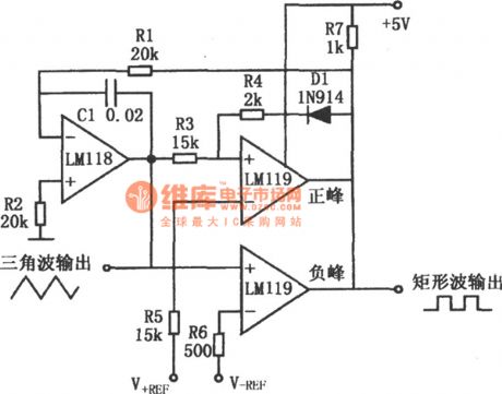
In the figure is a triangular wave generating circuit whose amplitude adjustment precision is ±0.01V. If a DC voltage is imposed on V+REF and V-REF, their amplitudes of the triangular wave are the peak the values of V+REF and V-REF, respectively. This circuit combines the integrator and two comparators which is used to judge the positive and passive peaks. If the output of the comparator on the positive terminal is positive, DI is locking on its own, and the output of the comparator on the passive peak is passive. If R1 was the potentiometer, the frequency would be changed and the amplitude is maintained. (View)
View full Circuit Diagram | Comments | Reading(483)
The single power supply sawtooth wave generator (556)
Published:2011/6/15 21:34:00 Author:Borg | Keyword: power supply, sawtooth wave generator
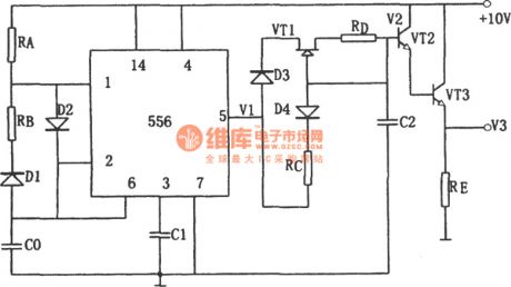
(View)
View full Circuit Diagram | Comments | Reading(769)
The sawtooth wave signal generator of D/A converter (DAC08EQ)
Published:2011/6/15 21:59:00 Author:Borg | Keyword: sawtooth wave, D/A converter
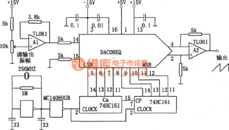
In the figure is the sawtooth wave signal generator of D/A converter. This circuit consists of the crystal oscillating circuit, counter and D/A converter. The crystal oscillating circuit delivers the signal to the counter, and the counter counts the number from 0, by each number that is counted, the D/A converter outputs an analog voltage of 1 step. When the number reaches the maximum value, it comes back to 0, and the analog comes back to 0, then the output voltage is increasing gradually, by which a precise sawtooth wave can be got. (View)
View full Circuit Diagram | Comments | Reading(620)
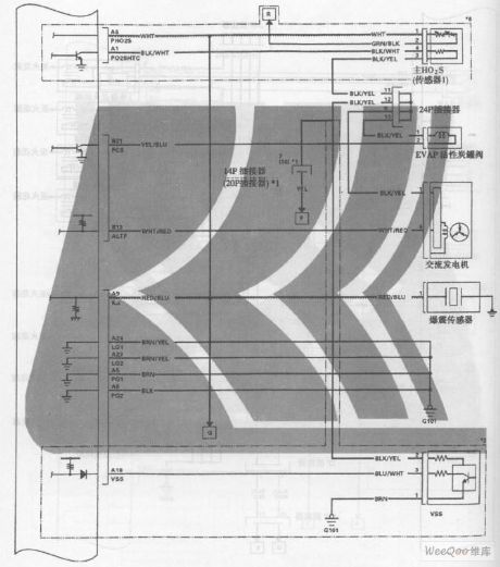
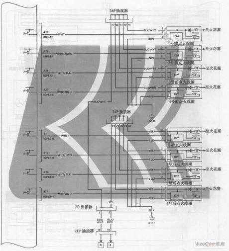
GuangZhou HONDA Fit saloon car engine circuit 8
Published:2011/6/19 19:01:00 Author:TaoXi | Keyword: GuangZhou, HONDA, Fit, saloon car, engine circuit
GuangZhou HONDA Fit saloon car engine circuit (View)
View full Circuit Diagram | Comments | Reading(459)
GuangZhou HONDA Fit saloon car engine circuit 5
Published:2011/6/19 19:02:00 Author:TaoXi | Keyword: GuangZhou, HONDA, Fit, saloon car, engine circuit
GuangZhou HONDA Fit saloon car engine circuit (View)
View full Circuit Diagram | Comments | Reading(412)
Vizi saloon car electric window and central lock circuit
Published:2011/6/28 19:17:00 Author:TaoXi | Keyword: Vizi, saloon car, electric window, central lock

Vizi saloon car electric window and central lock circuit is as shown in the figure:
(View)
View full Circuit Diagram | Comments | Reading(519)
GuangZhou HONDA Fit saloon car engine circuit 4
Published:2011/6/19 19:03:00 Author:TaoXi | Keyword: GuangZhou, HONDA, Fit, saloon car, engine circuit
GuangZhou HONDA Fit saloon car engine circuit (View)
View full Circuit Diagram | Comments | Reading(331)
GuangZhou HONDA Fit saloon car engine circuit 3
Published:2011/6/19 19:05:00 Author:TaoXi | Keyword: GuangZhou, HONDA, Fit, saloon car, engine circuit
GuangZhou HONDA Fit saloon car engine circuit (View)
View full Circuit Diagram | Comments | Reading(380)
GuangZhou HONDA Fit saloon car engine circuit 6
Published:2011/6/19 19:02:00 Author:TaoXi | Keyword: GuangZhou, HONDA, Fit, saloon car, engine circuit
GuangZhou HONDA Fit saloon car engine circuit (View)
View full Circuit Diagram | Comments | Reading(353)
| Pages:64/164 At 206162636465666768697071727374757677787980Under 20 |
Circuit Categories
power supply circuit
Amplifier Circuit
Basic Circuit
LED and Light Circuit
Sensor Circuit
Signal Processing
Electrical Equipment Circuit
Control Circuit
Remote Control Circuit
A/D-D/A Converter Circuit
Audio Circuit
Measuring and Test Circuit
Communication Circuit
Computer-Related Circuit
555 Circuit
Automotive Circuit
Repairing Circuit