
Automotive Circuit
Index 70
GuangZhou HONDA Fit saloon car ABS circuit 1
Published:2011/6/19 9:03:00 Author:TaoXi | Keyword: GuangZhou, HONDA, Fit, saloon car, ABS
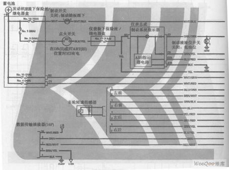
GuangZhou HONDA Fit saloon car ABS circuit (View)
View full Circuit Diagram | Comments | Reading(455)
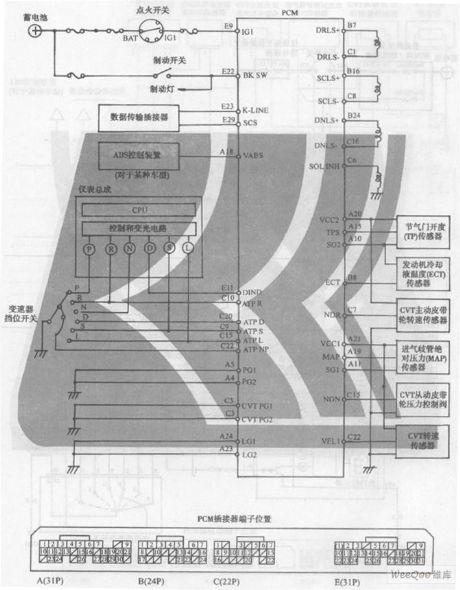
GuangZhou HONDA Fit saloon car 6-speed CVT circuit 2
Published:2011/6/19 9:01:00 Author:TaoXi | Keyword: GuangZhou, HONDA, Fit, saloon car, 6-speed, CVT
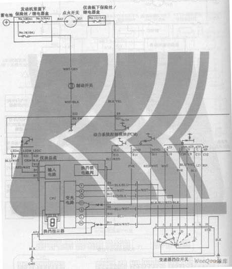
GuangZhou HONDA Fit saloon car 6-speed CVT circuit (View)
View full Circuit Diagram | Comments | Reading(446)
GuangZhou HONDA Fit saloon car 6-speed CVT + 7-speed mode circuit 3
Published:2011/6/19 8:58:00 Author:TaoXi | Keyword: GuangZhou, HONDA, Fit, saloon car, 6-speed, CVT, 7-speed mode,
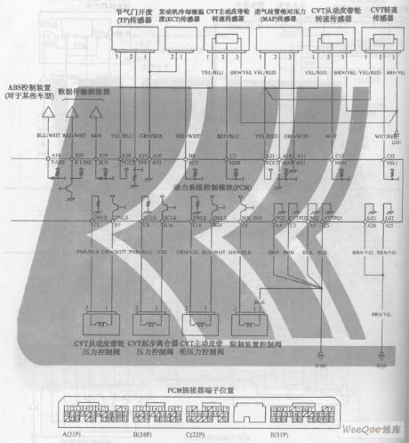
GuangZhou HONDA Fit saloon car 6-speed CVT + 7-speed mode circuit (View)
View full Circuit Diagram | Comments | Reading(504)
GuangZhou HONDA Fit saloon car 6-speed CVT circuit 3
Published:2011/6/19 9:02:00 Author:TaoXi | Keyword: GuangZhou, HONDA, Fit, saloon car, 6-speed, CVT
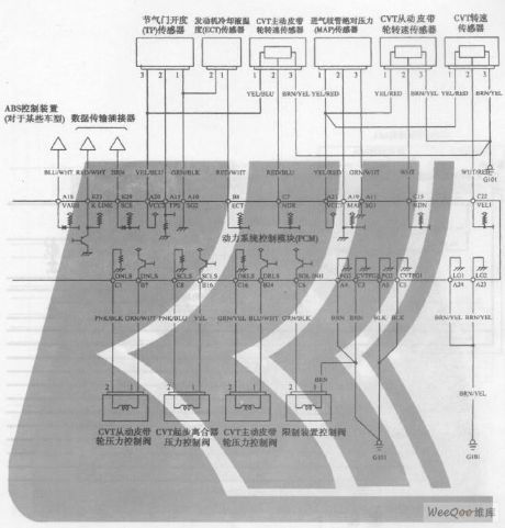
GuangZhou HONDA Fit saloon car 6-speed CVT circuit (View)
View full Circuit Diagram | Comments | Reading(410)
GuangZhou HONDA Fit saloon car 6-speed CVT circuit 1
Published:2011/6/19 8:59:00 Author:TaoXi | Keyword: GuangZhou, HONDA, Fit, saloon car, 6-speed, CVT
GuangZhou HONDA Fit saloon car 6-speed CVT circuit (View)
View full Circuit Diagram | Comments | Reading(474)
KESTX02--The ASK emitter circuit of 320~290 MHz
Published:2011/6/25 4:34:00 Author:qqtang | Keyword: ASK, emitter
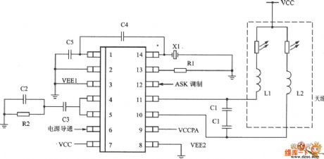
KESTX02--The ASK emitter circuit of 320~290 MHz is shown as above.
(View)
View full Circuit Diagram | Comments | Reading(371)
ZhongHua saloon car engine circuit 2
Published:2011/6/19 8:52:00 Author:TaoXi | Keyword: ZhongHua, saloon car, engine
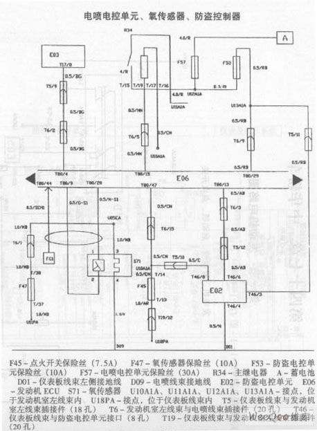
ZhongHua saloon car engine circuit (View)
View full Circuit Diagram | Comments | Reading(475)
ShangHai General WuLing car vehicle electrical system circuit 2
Published:2011/6/19 8:48:00 Author:TaoXi | Keyword: ShangHai, General, WuLing, car, vehicle electrical system
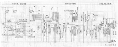
ShangHai General WuLing car vehicle electrical system circuit (View)
View full Circuit Diagram | Comments | Reading(517)
ShangHai General WuLing car vehicle electrical system circuit 1
Published:2011/6/19 8:48:00 Author:TaoXi | Keyword: ShangHai, General, WuLing, car, vehicle electrical system
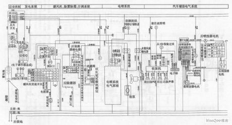
ShangHai General WuLing car vehicle electrical system circuit (View)
View full Circuit Diagram | Comments | Reading(475)
ShangHai General WuLing car united electronic & electronic control system circuit
Published:2011/6/19 8:41:00 Author:TaoXi | Keyword: ShangHai, General, WuLing car, united electronic, electronic control system
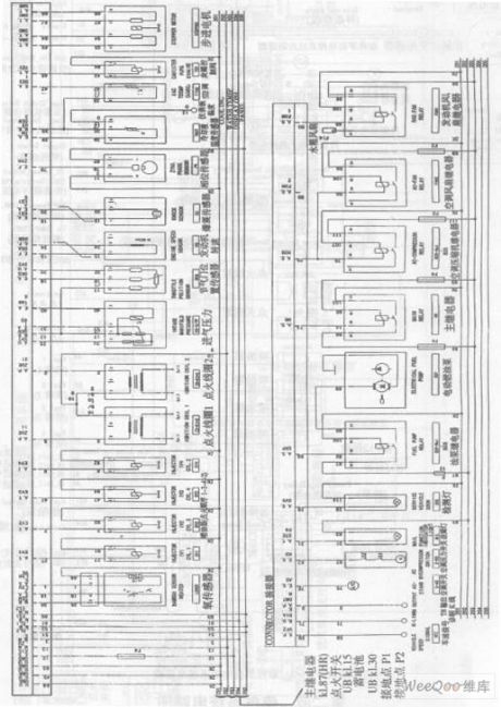
ShangHai General WuLing car united electronic & electronic control system circuit (View)
View full Circuit Diagram | Comments | Reading(435)
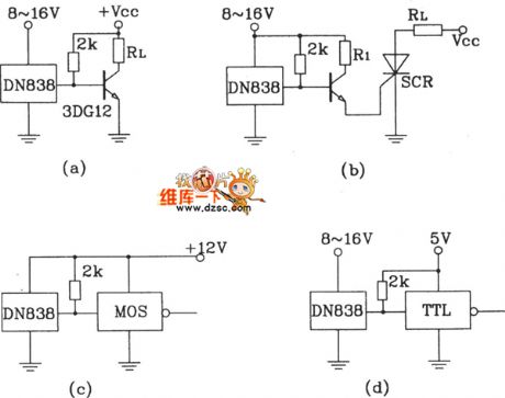
ND838 several typical application circuit
Published:2011/6/25 10:00:00 Author:John
View full Circuit Diagram | Comments | Reading(515)
MC-1350P preamplifier circuit
Published:2011/6/21 0:26:00 Author:John | Keyword: preamplifier
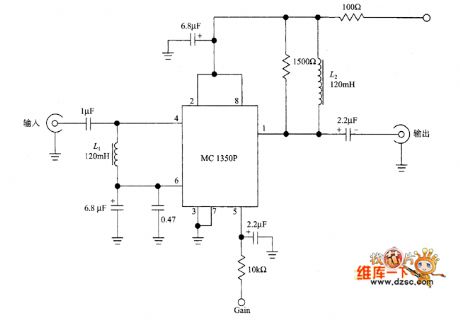
MC-1350P preamplifier circuit is shown.
(View)
View full Circuit Diagram | Comments | Reading(995)
transistor pre-amplifier with feedback NPN circuit
Published:2011/6/17 9:37:00 Author:John | Keyword: transistor, pre-amplifier
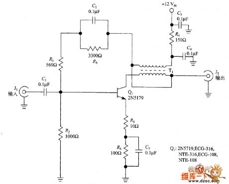
RF amplifier has very versatile functions, which can be used as the receiver’s preamplifier working in the 3 ~ 30MHz short wave band. It also can be used as post amplifier for filter, mixer and other equipment with band attenuation factor. Mixers and crystal filters often have 5 ~ 8dB loss of signal (called insertion loss), then the amplifier can overcome these losses. Meanwhile, the amplifier can also improve oscillator circuit’s output level of the signal generator. In this section, it can be used alone in a separate shielded container and also can be included as a part of the oscillator circuit.
(View)
View full Circuit Diagram | Comments | Reading(1120)
Receiver input network equivalent circuit
Published:2011/6/21 0:23:00 Author:John | Keyword: Receiver, input net
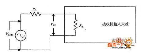
Receiver input network equivalent circuit is shown. (View)
View full Circuit Diagram | Comments | Reading(470)
SBL-1-1 DBM top-level direct conversion receiver audio mixer circuit
Published:2011/6/16 10:28:00 Author:John | Keyword: audio mixer, direct conversion receiver
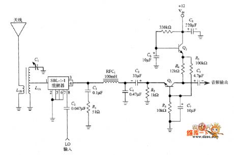
The following figure shows the Lawellen’s another simplified design (original design includes QRP transmitter and DCR). This designed front-end circuit includes an RF and a tuned secondary transformer (L1A). Secondary transformer is raised to resonant state through capacitor C1 and is contacted with 50Ω. Such is to match the input impedance with double-balanced mixer (DBM: Double Balanced Mixer).
DBM used here is Mini-Circuits SBL-1-1. But for the original DBM, Lawllen form it by combining the toroidal transformer and the diode. (View)
View full Circuit Diagram | Comments | Reading(8999)
NE-602 direct conversion receiver complete circuit
Published:2011/6/16 0:17:00 Author:John | Keyword: direct conversion receiver
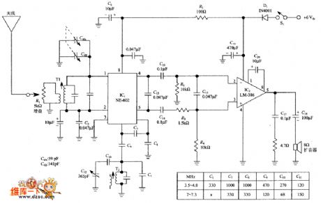
The figure below shows the design of Dillon. NE-602's push-pull output (referring to the simultaneous use of pin 4 and pin) is utilized, which is more advanced than the single-ended output. Dillon points out that the balanced output enhances performance, especially for the inhibition on AMBOB breakthrough. Meanwhile, the helpful device for the AM break is the 0.47μF capacitor across the NE-602 output ends.
NE-602 direct conversion receiver complete circuit (View)
View full Circuit Diagram | Comments | Reading(5422)
Direct conversion receiver partial circuit
Published:2011/6/16 0:12:00 Author:John | Keyword: Direct conversion receiver

The figure shows the simplest form of NE-602 DCR basic circuit. There are multiple structures of the input parts and local oscillator partial circuits. The figure shows the most common one. Output signal is led from pin 4 or pin 5 and is feedback to the audio amplifier. This circuit can work but not be recommended, because the circuit will be relatively with large noise and image signal and no filtering.
Figure: NE-602 Direct conversion receiver partial circuit (View)
View full Circuit Diagram | Comments | Reading(1013)
The pulse generating circuit composed of phase-lock loop
Published:2011/6/16 20:40:00 Author:qqtang | Keyword: pulse generating circuit, phase-lock loop
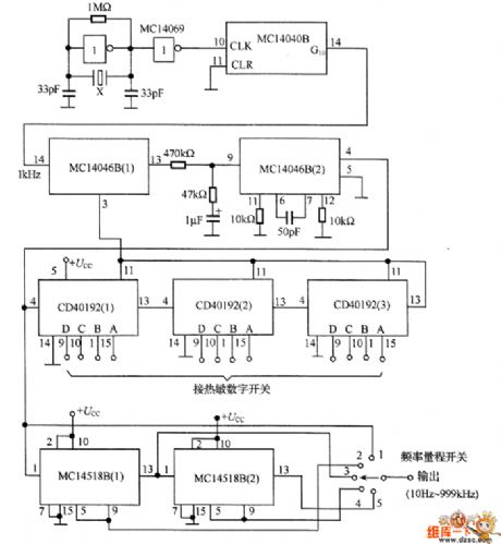
The output frequency of the circuit is 10Hz~999kHz, the frequency precision is 3-bit and adjustable. In the circuit, MCl4046B(1) is the phase comparator, MC14046B(1) is the voltage control oscillator. There are two types of comparators in MC14046B, if the phase clock φ2 is used, the frequency range is 1:1000, to be simple, the maximum adjustable range is 1:10 here. It uses 3-bit digital switch to control the 3 decimal counter, i.e the frequency splitting constants composed of CD40192(1), CD40192(2) and CD40192(3) which set the frequency value.
(View)
View full Circuit Diagram | Comments | Reading(711)
The 3-key interlock electric switch circuit
Published:2011/6/23 6:26:00 Author:qqtang | Keyword: interlock, electric switch

View full Circuit Diagram | Comments | Reading(617)
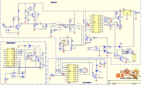
The remote control energy-saving lamp, wireless support and infrared remote control circuit
Published:2011/6/19 20:32:00 Author:qqtang | Keyword: energy-saving lamp, infrared remote control
View full Circuit Diagram | Comments | Reading(500)
| Pages:70/164 At 206162636465666768697071727374757677787980Under 20 |
Circuit Categories
power supply circuit
Amplifier Circuit
Basic Circuit
LED and Light Circuit
Sensor Circuit
Signal Processing
Electrical Equipment Circuit
Control Circuit
Remote Control Circuit
A/D-D/A Converter Circuit
Audio Circuit
Measuring and Test Circuit
Communication Circuit
Computer-Related Circuit
555 Circuit
Automotive Circuit
Repairing Circuit