
Automotive Circuit
Index 80
Remote control toy car transmitter circuit
Published:2011/6/4 9:59:00 Author:John | Keyword: Remote control toy car

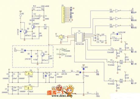
Remote control toy car transmitter circuit is shown below.
Potentiometer RV1 controls left and right wheels. Potentiometer RV2 controlsfront andrear wheels. Potentiometer RV3 makes slight adjustment forleft and right wheels. Potentiometer RV4makes slight adjustment for front andrear wheels. (View)
View full Circuit Diagram | Comments | Reading(4641)
Pulse start single stable circuit
Published:2011/6/4 10:47:00 Author:John
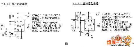
Pulse start single stable circuit can be divided into two different units. Two different units both are RT-7.6-CT and are input from end 2. 1.2.1. End 2 in the circuit has no components and is the simplest form. 1.2.2 Circuit has a differential circuit with RC.
1)Features: “RT-7.6-CT”, external pulse start or manual start.2)Formula: Td=1.1 RT*CT3)Functions: timing, time delay, flutter elimination, frequency division, frequency multiplication, strobe output and inspection for L、C rate
1)Features: “RT-7.6-CT”, external pulse start inputs to differential circuit with RC.2)Formula: Td=1.1 RT*CT3)Functions: timing, time delay, flutter elimination, frequency division, frequency multiplication, strobe output and inspection for L、C rate
(View)
View full Circuit Diagram | Comments | Reading(445)
Manual starting monostable circuit
Published:2011/6/4 10:58:00 Author:John
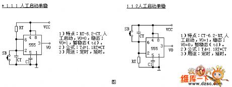
Manual starting monostable circuit is divided into two different units according to locations of timing resistor and timing capacitor. These two units are coded by 1.1.1 and 1.1.2 respectively. In the form of their input ends, that is to say that the structural characteristics of the circuit are: RT-6.2-CT and CT-6.2-RT .
1)Features: “RT-6.2-CT”, manual start,V0=0,steady-state;V0=1, temporary steady-state(td).2)Formula: Td=1.1 RT*CT3)Functions: timing and time delay.
1)Features: “CT-6.2-RT”, manual start,V0=0,steady-state;V0=1, temporary steady-state(td).2)Formula: Td=1.1 RT*CT3)Functions: timing and time delay.
(View)
View full Circuit Diagram | Comments | Reading(444)
Ring counter sequence pulse generator circuit
Published:2011/6/4 11:04:00 Author:John | Keyword: ring counter, sequence pulse generator
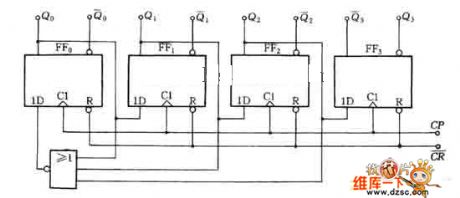
Ring counter sequence pulse generator circuit, just as shown in the figure, is a 4-output sequence pulse generator composed by a four-bit ring counter.
(View)
View full Circuit Diagram | Comments | Reading(1169)
Quartz multivibrator circuit
Published:2011/6/4 13:15:00 Author:John | Keyword: Quartz multivibrator
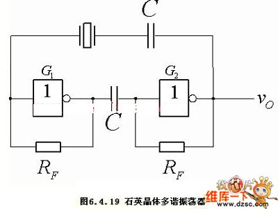
Figure: Quartz multivibrator circuit (View)
View full Circuit Diagram | Comments | Reading(607)
Hainan Mazda parking sensor circuit
Published:2011/6/5 Author:John | Keyword: parking sensor
Hainan Mazda parking sensor circuit is shown below.
(View)
View full Circuit Diagram | Comments | Reading(2202)
the circuit of auto water supplier for agriculture(1)
Published:2011/6/4 20:41:00 Author:Ariel Wang | Keyword: auto, water, supplier, agriculture
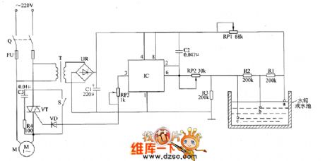
When the knife switch Q gets through,AC 220V voltage is reduced by T,commuted by UR and filtered by C1.It provides 10V DC voltage(Vcc) for input circuit and control circuit of water level detection.When the water level of the water tank reaches electrode b,the resistence of water will be short-circuit by R2.It makes the voltage of IC's 2nd-pin and 6th-pin higher than Vcc/3,but lower than 2Vcc/3(about Vcc/2).The inner circuit sets up.The 3rd-pin still output high level.VT stays conducted.Electric motor of water pump M goes on pumping.When the water level of the water tank reaches electrode a,the resistence of water will be short-circuit by R1.It makes the voltage of IC's 2nd-pin and 6th-pin higher than 2Vcc/3.It makes the high level of 3rd-pin jump to low level.VT stops. M is power-off .And it stops pumping.
(View)
View full Circuit Diagram | Comments | Reading(496)
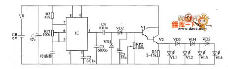
the circuit of electrifying intermittent controller part 4
Published:2011/6/5 9:25:00 Author:Ariel Wang | Keyword: electrifying, intermittent, controller
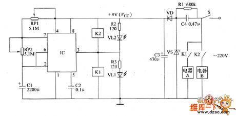
At the moment of the mains power supply gets through,the voltage of C1 can't be changed suddenly.IC's 2nd-pin is low level(lower than Vcc/3),3rd-pin outputs high level.It conducts K1 to pull in. Its open point is switch in.The electric appliance A is conducted to work.At the same time VLI is lighted.After that,+9V voltage charges C1 by RP1 and RP2.It makes the voltage of C1 goes up and up.When the voltage is beyond 2Vcc/3.The in-circuit turns over.The 3rd-pin turns high level to low level.K1 releases.K2 pulls in.Electric appliance A stops working.Electric appliance B is conducted to work.At the same time,VL1 dies out.VL2 is lighted.
(View)
View full Circuit Diagram | Comments | Reading(458)
the circuit of electrifying intermittent controller part 3
Published:2011/6/6 2:02:00 Author:Ariel Wang | Keyword: electrifying , intermittent, controller
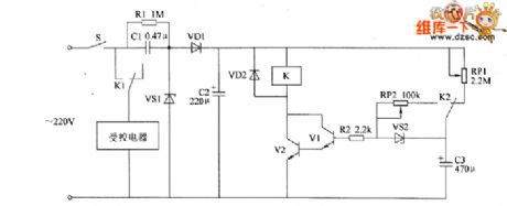
When the mains switch S gets through,AC 220V voltage is reducted by C1.It is regulated by VS1.It is commutated by VD1.And it is filtered by C2.Then it generates about 15V DC working voltage.It provides voltage for relay K .It charges CS by RP1.When the voltage of C3 reaches a certain value.VS2 conducts. V1 and V2 is saturated to conduct. The normally closed contact is disconnected.The controlled appliances(for example ,low power electric heater,electric motor of water pump,oxygen enrichment equipment,scavenger fan and humidifier ect) are conducted to work.C3 discharges base electrode of V1 by RP2 and R2.So V1 and V2 stay conducted.The controlled appliances go on to work. (View)
View full Circuit Diagram | Comments | Reading(461)
the circuit of humidity detector for food part 2
Published:2011/6/6 1:24:00 Author:Ariel Wang | Keyword: humidity, detector, food
When to be detected,the graininess foodstuffs are put into the two plate electrodes of the capacitive humidity sensor .The air medium between two plate electrodes turns to dissipation change.It changes the capacitance.The oscillation frequency of multivibrator changes at the same time.The more humidity amount of foodstuffs ,the smaller amount of the sensor.And oscillation frequency of the multivibrator will become faster.The DC voltage of V1 base electrode becomes higher.The output voltage of V2 emitter becomes higher.LED(VL1-VL4) will give more light.
(View)
View full Circuit Diagram | Comments | Reading(420)
the control circuit of electric fence part 3
Published:2011/6/6 9:22:00 Author:Ariel Wang | Keyword: control , electric , fence

When DC current power-supply is adopted,S1 and S2 get through.The self-exciting multivibrator works.It turns 6V DC voltage to the swing of 60V square-wave voltage by T2.The square wave voltage is commutated by UR and it is filtered by C1.It charges C3 and C2 by R3 and R4.When the voltage of C3 reaches the break over voltage of DIAC V3.V3 is conducted.C3 discharges the gate of thyristor VT by V3.It triggers VT to conduct.After VT is conducted,the electric charge stored on C2 discharges quickly by VT and T3.It generates pulse high voltage on the secondary winding of T3.
(View)
View full Circuit Diagram | Comments | Reading(1211)
the control circuit of electric fence part 4
Published:2011/6/6 1:56:00 Author:Ariel Wang | Keyword: control, electric, fence

When the mains switch S gets through,the battery GB provides the whole machine all connected circuit +6V voltage.The pulse generator will generate narrow pulse voltage signal after it is conducted to work.It is buffered to amplifier by V1 .Then it will drive V2.It makes V2 at a switch state of whether conducted or stopped.It will control the pulse current which goes into the primary winding of T.The pulsed high voltage generated by the secondary winding of T goes to the bare wire of electric fence.When the electric quantity of the storage battery is enough,VS and V3 are conducted.The 8th-pin of IC becomes low level.V4 stops.VL is not lighted.HA doesn't give a sound.
(View)
View full Circuit Diagram | Comments | Reading(1366)
the circuit of soil humidity monitor part 1
Published:2011/6/2 1:02:00 Author:Ariel Wang | Keyword: soil, humidity , monitor
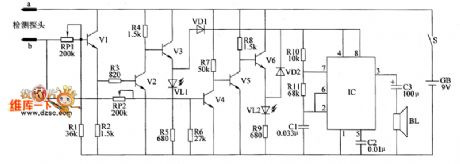
When the soil is too wet(the humidity is over the value of upper limit set by RP2),the resistance between two humidity probe electrodes reduces.It makes V1,V2 and V4 conducted of saturation.It stops V3 and V5 .It conducted V6.It lights VL2.Those indicate the humidity of the soil is too high..At the same time,VD2 is conducted.The audiofrequency oscillator works,BL will ring.
When the soil is too dry(the humidity is lower than the value of low limit set by RP1),the resistance between two humidity probe electrodes increases.It makes V3 and V5 conducted of saturation.It stops V1 ,V2,V4 and V6 .It conducted V6.It lights VL1.Those indicate the humidity of the soil is too low.At the same time,VD1 is conducted.The audiofrequency oscillator works,BL will ring.
(View)
View full Circuit Diagram | Comments | Reading(635)
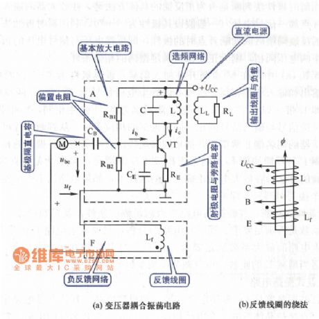
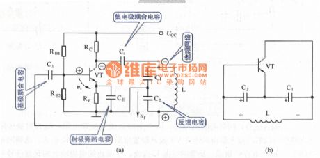
Transformer Coupling Oscillation Circuit
Published:2011/5/20 1:38:00 Author:Michel | Keyword: Transformer, Coupling Oscillation, Circuit
View full Circuit Diagram | Comments | Reading(463)
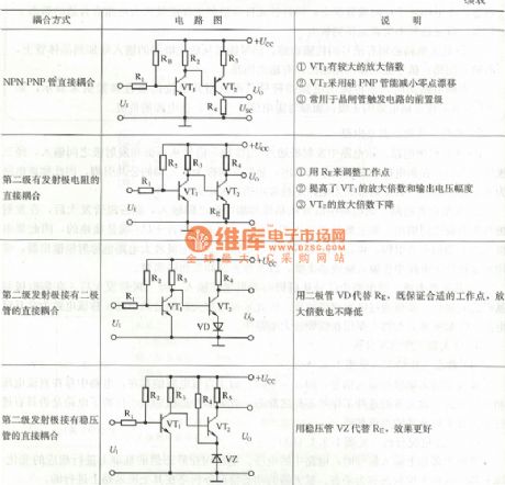
Dynatron Coupling Circuit
Published:2011/5/20 1:33:00 Author:Michel | Keyword: Dynatron Coupling, Circuit
View full Circuit Diagram | Comments | Reading(515)
Capacitance Three-point Concussion Circuit
Published:2011/5/20 1:45:00 Author:Michel | Keyword: Capacitance, Three-point, Concussion Circuit
View full Circuit Diagram | Comments | Reading(422)
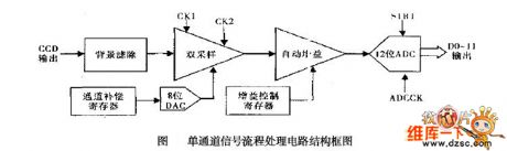
structure circuit of single-channel signal processing
Published:2011/6/1 2:28:00 Author:chopper | Keyword: structure circuit, single-channel signal processing
View full Circuit Diagram | Comments | Reading(468)
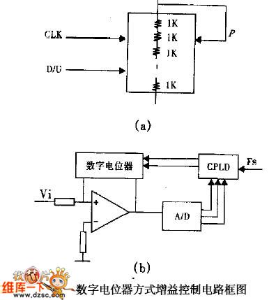
Gain Control Circuit with Digital Potentiometers
Published:2011/6/1 2:11:00 Author:chopper | Keyword: Gain Control, Digital Potentiometers
View full Circuit Diagram | Comments | Reading(443)
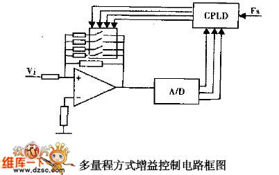
multrirange gain control circuit
Published:2011/5/29 22:12:00 Author:chopper | Keyword: multrirange, gain control
View full Circuit Diagram | Comments | Reading(399)
the circuit of soil humidity monitor part 2
Published:2011/6/1 6:40:00 Author:Ariel Wang | Keyword: soil , humidity, monitor
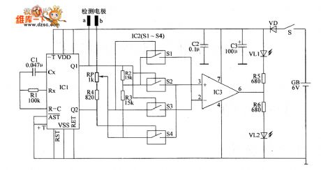
When mains switch S got through,actable multivibrator vibrates(the vibration frequency is 58Hz).From Q1 end to Q2 end of IC1,it alternately outputs high level and low level.When the Q1 end of IC1 outputs high level,the Q2 end of Q2 end outputs low level,the internal electronic switch S2 is connected with S3;when the Q2 end of IC1 outputs high level,the Q2 end of Q2 end outputs low level,the internal electric switch 51 is connected with 54.The reference voltage is generated by the branch voltage after R2 and R3 in series.It adds to 2nd-pin (reversed-phase input end) and 3rd-pin(normal phase input end) of IC3 by electronic switch S1. (View)
View full Circuit Diagram | Comments | Reading(450)
| Pages:80/164 At 206162636465666768697071727374757677787980Under 20 |
Circuit Categories
power supply circuit
Amplifier Circuit
Basic Circuit
LED and Light Circuit
Sensor Circuit
Signal Processing
Electrical Equipment Circuit
Control Circuit
Remote Control Circuit
A/D-D/A Converter Circuit
Audio Circuit
Measuring and Test Circuit
Communication Circuit
Computer-Related Circuit
555 Circuit
Automotive Circuit
Repairing Circuit