Automotive Circuit
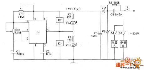
the circuit of electrifying intermittent controller part 4
Published:2011/6/5 9:25:00 Author:Ariel Wang | Keyword: electrifying, intermittent, controller | From:SeekIC

At the moment of the mains power supply gets through,the voltage of C1 can't be changed suddenly.IC's 2nd-pin is low level(lower than Vcc/3),3rd-pin outputs high level.It conducts K1 to pull in. Its open point is switch in.The electric appliance A is conducted to work.At the same time VLI is lighted.After that,+9V voltage charges C1 by RP1 and RP2.It makes the voltage of C1 goes up and up.When the voltage is beyond 2Vcc/3.The in-circuit turns over.The 3rd-pin turns high level to low level.K1 releases.K2 pulls in.Electric appliance A stops working.Electric appliance B is conducted to work.At the same time,VL1 dies out.VL2 is lighted.
Reprinted Url Of This Article:
http://www.seekic.com/circuit_diagram/Automotive_Circuit/the_circuit_of_electrifying_intermittent_controller_part_4.html
Print this Page | Comments | Reading(3)

Article Categories
power supply circuit
Amplifier Circuit
Basic Circuit
LED and Light Circuit
Sensor Circuit
Signal Processing
Electrical Equipment Circuit
Control Circuit
Remote Control Circuit
A/D-D/A Converter Circuit
Audio Circuit
Measuring and Test Circuit
Communication Circuit
Computer-Related Circuit
555 Circuit
Automotive Circuit
Repairing Circuit
Code: