
Automotive Circuit
Index 76
The fault detection circuit of Santana AJR engine
Published:2011/6/10 3:22:00 Author:Borg | Keyword: fault detection circuit, Santana
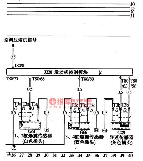
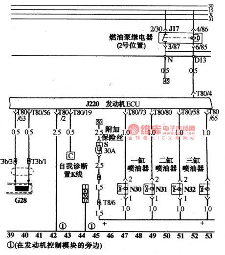
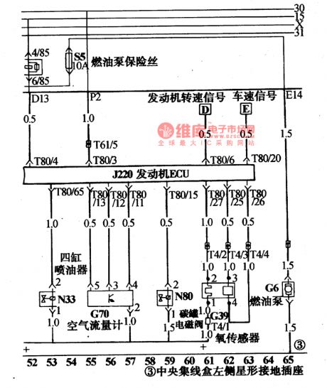
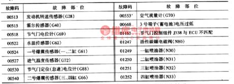
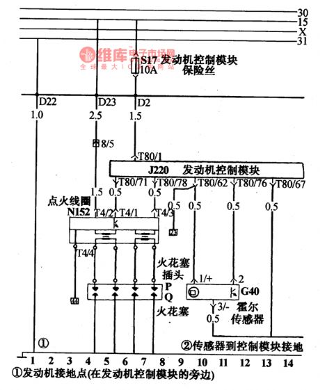
The computer J220 of the AJR engine can save the fault of sensors and executing components, and the fault codes have to be read out by VAG1552 or VAG1551 fault detectors or other multiple code readers which are produced by Volkswagon AG. The figure and instructions of VAG1551 fault detector have been narrated in the power jet circuit of Santana 20OOGLi. VAG1552 is up-grated on the basis of VAG1551, and the size is smaller, functions are more complete, the figure of it is like a laptop.
(View)
View full Circuit Diagram | Comments | Reading(526)
The relay and fuse circuit on the top of Santana central connection box
Published:2011/5/18 22:16:00 Author:Borg | Keyword: relay, fuse, central connection box, Santana

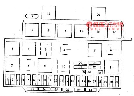
The central connection box is the connecting linchpin of the whole car, which is at the acetabulum under the instrument plate. There are more than 20 relays and more than 30 fuses fixed on the surface of the box, while more than 10 connectors on the ground of it. The inside surface is an insulated PVC box inlaid with copper bars of layers, separated or linked, which formthemainstream circuit centralized with igniting switches, and connectors are linked with the front and rear part of the car and instrument bundles respectively. The positions of relays and fuses are shown in Figure 2-1(notes: chassis No. is 32MP003182).
(View)
View full Circuit Diagram | Comments | Reading(535)
The component detection circuit of Daewoo ESPERO igniting system
Published:2011/5/18 22:18:00 Author:Borg | Keyword: detection circuit, Daewoo ESPERO, igniting system


Both the high voltage wires of *1 and *2 should be checked to make sure that the wire of spark piston is connecting. If sparks come out when EST plug(wire 4) is being pull off, that means the output voltage of signal picking coil is too low to make EST work. If *3 has sparks, that means the problem is in electricity distributor and spark distributor. When the *4 is in normal condition, there should be battery voltage on both terminals c and + of igniting module, and the voltage is tend to be low, that mean there are breaks or resistance value is too high between distributor and igniting coil or switch.
(View)
View full Circuit Diagram | Comments | Reading(1551)
The fault diagnosis circuit of Daewoo-ESPERO fuel pump relay
Published:2011/5/18 22:22:00 Author:Borg | Keyword: fault diagnosis circuit, Daewoo-ESPERO

When the igniting switch is at the ON gear, computer ECM will start the fuel pump relay and run the pump in the oil box. When the engine starts or runs, if ECM receives the igniting reference pulse signal, the fuel pump will go on to work; if there is no reference pulse signal, then the ECM will shut down the pump in 2 secondsafter the igniting switch is on.
It will lead to a long starting time of the engine if the oil pump relay doesn't work, especially when the temperature of the engine is low or the engine oil viscosity is high.
(View)
View full Circuit Diagram | Comments | Reading(1897)
Buick Century lighting and singal circuit diagram(2)
Published:2011/5/16 3:40:00 Author:Nicole | Keyword: Buick Century, lighting, singal

Buick Century car reversing lamp circuit diagram(2) (View)
View full Circuit Diagram | Comments | Reading(409)
Buick Century lighting and singal circuit diagram(1)
Published:2011/5/16 3:42:00 Author:Nicole | Keyword: Buick Century, lighting, singal

Buick Century car steering signal and danger signal, parking lamp circuit diagram(1) (View)
View full Circuit Diagram | Comments | Reading(460)
The oil pump control system circuit of Tianjin Xiali TJ710OE
Published:2011/5/26 22:04:00 Author:Borg | Keyword: oil pump, control system, Tianjin Xiali

When the igniterisat the starting gear, or the in 2s after the engine crankshaft steering signals are delivered to ECU, then ECU will connect the oil pump relay terminals FC2 with the ground connection and the oil pump gets into working. This will make sure the oil pump runs only under the condition that the engine is working, therefore, power consumption and friction are diminished. See as the figure: the oil pump control system circuit
(View)
View full Circuit Diagram | Comments | Reading(426)
The power supply and igniting system circuit of Tanjin Xiali TJ7100 and 7100U
Published:2011/5/26 22:04:00 Author:Borg | Keyword: power supply, igniting system, Tanjin Xiali

Xiali 12V electric system is single-line, negative ground connection, the model of the battery is 6-QA-45. There is a thick wire on it's positive point connecting with the stater, and another 3 linking to a connector, and the fuses of a,b and c divide the circuit into 3, see as Figure 1 to Figure 3.Fuse a , specification is 0.85mm, volume 60A. It links to the fire wire of the AC motor, igniting switch (27), brake lamp (24), interior lamp(25), clock(43), width lamp (57 and 59) and instrument light(61),etc.Fuse b , specification is 0.5mm, volume 40A
(View)
View full Circuit Diagram | Comments | Reading(387)
Daewoo RACER car rear window defroster circuit diagram
Published:2011/5/16 3:24:00 Author:Nicole | Keyword: Daewoo RACERcar, rear window, defroster

(8)rear window defroster(as shown in the figure10)
When the touch switch S16 is connected one time, it can make the timing relay K7 contact point close for 10 minutes, then the rear window defroster resistance curve is energizing and heating, at the same time, LED of S16 switch turns on, after 10 minutes, the circuit is cut off automatically. If you want to cut off it early, you can touch it again.
(View)
View full Circuit Diagram | Comments | Reading(1442)
The air-conditioning circuit of DPCA-VOLCANE DC714OZX(see as Figure 1-a, 1-1b,2-a and 2-b)
Published:2011/5/19 21:45:00 Author:Borg | Keyword: air-conditioning circuit, DPCA-VOLCANE


Figure 1-a the principle air-conditioning circuit of DPCA-VOLCANE DC714OZX53-water temperature controller; 141-air-conditioning amplifier; 225-compressor magnetic clutch; 431-idling speed improving magnetic valve; 582-cold air(A/C) switch; 813-fan low-speed relay; 814-fan transmission relay; 912-evaporator temperature sensor; L2-fusible links
Figure 1-b the principle air-conditioning circuit of DPCA-VOLCANE DC714OZX(extend)40h-water warning lamp
(View)
View full Circuit Diagram | Comments | Reading(431)
The headlight circuit of Daewoo Racer
Published:2011/5/26 22:05:00 Author:Borg | Keyword: headlight circuit, Daewoo Racer

1.see as the figure, all the lights are under the control of switch S4. 0 gear means off. By relay K3, 1 gear connects No.58 circuit: width E7~ElO、E13 and E14, instrument lamps E41~E44, license lamp E11 and El2, glove box lamp E26 and igniter E27 can get through. When it is at 2 , besides the above lamps, it gets through the No.56 circuit by the relay K4, and the headlight is on. The dimmer overtaking switch(s5) can control high beams(E3 and E5) or low beams(E4 and E6), the overtaking signal is delivered by pressing key to get through E3 and E5.
See as the figure. the headlight circuit of Daewoo Racer (View)
View full Circuit Diagram | Comments | Reading(1232)
The wiper and washer circuit of DPCA-VOLCANE DC714OZX
Published:2011/5/19 21:48:00 Author:Borg | Keyword: wiper and washer circuit, DPCA-VOLCANE


When the igniting switch(300) is normally working, the wire of 2G1 will link to the switch of 212. (Including the fusebox FZ), there are 5 gears in the switch. In the frontend of the marked position in the figure, 1 means stepper gear( single step work ), 0 means stopping working, J means interrupted wiping. The interval relay(962) controlled circuit works when it links to the power supply fire wire, and the wiper motor(694) was controlled by the switch of 212; the interval motor(962) terminal is designed to connect with the fire wire, and the motor wipe 1-2 times at a low speed, then keep still for 6-8s, and wipe again 1-2 times, then keep still for 6-8s```
(View)
View full Circuit Diagram | Comments | Reading(435)
TDA610Q(ICNBOl) pin functions and data circuit
Published:2011/5/11 2:06:00 Author:TaoXi | Keyword: pin functions, data


The TDA4605-3 is designed as one kind of switch power supply thick-film integrated circuit that can be used in Philips G8 movement (such as the 25SX8661/93T, 28SX8671/93P), the Goldstar MC-15A movement (CFT一2590), the Dimethoate CT6388M, the Peony 64C2A, T4C2, the Konka F2566E, nlOgE, A1488N, the Changhong NC6 movement (G2966A, G2967A).etc.
The TDA4605-3 has the sampling voltage processing regulator circuit, the under-voltage detection and protection circuit, the excitation pulse output circuit, the soft-start control circuit.etc. This IC is in the 8-pin package, the pin functions and data is as shown in table 16.
Table 16 The pin functions and data of the TDA4605-3
(View)
View full Circuit Diagram | Comments | Reading(1186)
TDA610lQ integrated block internal box circuit
Published:2011/5/11 2:10:00 Author:TaoXi | Keyword: integrated block, internal box


The TDA4665 and TDA4665T are designed as the baseband delay IC that is produced by the PHILIPS company, and it can be used in a variety of domestic multi-system TVs.
The TDA4665 and TDA4665T use the switch capacitor technology, there are two filters to do one line time delay (64 us). The integrated block internal box circuit and the typical application in Haier 692-733AA TV are as shown in figure 12. This IC is in the 16-pin DP DIP package or 16-pin scaled type flat package, the pin functions and data of this circuitare as shown in table 15.
(View)
View full Circuit Diagram | Comments | Reading(765)
the circuit of the automatic water supplier for agriculture part 2
Published:2011/6/8 8:02:00 Author:Ariel Wang | Keyword: automatic , water supplier , agriculture

When knife-like switch and mains switch get through ,the AC 220V voltage between L1 end and N end is reduced by T.Then it generates AC 12V voltage .It is the working voltage of HL1 and HL2.At the same time ,it provides DC 12V working voltage for the detection of water level after it is commutated and filtered by UR.When the controlled water level lowers to the low water level,the permanent magnet placed on the float approaches SAI.The contacts of SAI are conducted by magneticaction of permanent magnet.VI is conducted by triggering.K1 pulls in after it is conducted.The normally open contacts K1-l and Kl-2 are connected.It lights HL2.It pulls in KM.The electric pump M works.It begins to pump.
(View)
View full Circuit Diagram | Comments | Reading(422)
the circuit of the monitor for humidity and temperature of seedling raising greenhouse
Published:2011/6/9 6:35:00 Author:Ariel Wang | Keyword: monitor, humidity, temperature, seedling raising greenhouse

When the soil is too wet(the humidity is over the value of upper limit set by RP1),not gate D2 will output high level,not gate D3 will output low level.It lights LED .This indicates the humidity of the soil too high.At the same time,audio alarm circuit works.BL rings.When the soil is too dry(the humidity is lower than the value of low limit set by RP2),not gate D1 will output low level.It lights VL1 .This indicates the humidity of the soil too low.At the same time,audio alarm circuit works.BL rings.
(View)
View full Circuit Diagram | Comments | Reading(460)
the circuit of the electrifying intermittent controller part 1
Published:2011/6/9 6:36:00 Author:Ariel Wang | Keyword: electrifying, intermittent, controller

When the power-supply is turned on,the AC 220V voltage is reduced by C1.It is commutated by UR.After it is filtered by C3,it branched into 3 parts.One part is current limited by R11.It is regulated by VS1.It provides 12V working voltage for relay K.One part is current limited by R1 and R2.It is regulated by VS2,it provides +5.6V working voltage for IC.The last part light VL3 through Ⅲ.After IC is conducted to work,the 8th-pin outputs low level.It lights VL2.It stops VI and Y3.V2 is conducted.K can't be pulled in. The load is not working.VL1 is lighted.You can adjust the resistance of RP1.Or you can change the capacity of C2.You can set up the time of the load whenit ispower down(the range of adjusting is 5-120min).
(View)
View full Circuit Diagram | Comments | Reading(1093)
the control circuit of electric fence part 2
Published:2011/6/9 6:40:00 Author:Ariel Wang | Keyword: control, electric, fence

One part of the 220V AC voltage is reduced by T1.It is commutated by VD1 and it is filtered by C1.The other part is commutated by VD1.It is current limited by R1.It is filtered by C2.It provides power supply for the circuit of high voltage generator.When the impulsator gets to work,The frequency of electric impulse signal which outputs from the 3rd-pin of IC is 2Hz .It goes to the gate pole of thyristor VT by R4 and C5.So the VT is conductedy or stopped periodicity by the changing of the pulse signal.When VT is conducted,C2 discharges by the low voltage winding (winding W1) by step-up transformer.It generates pulsed high voltage on the high voltage winding of T2(winding W2).It discharges by the discharge spark interval F1 and F2. (View)
View full Circuit Diagram | Comments | Reading(2260)
The FAW Toyota-Reiz engine control diagram (2)
Published:2011/6/9 0:16:00 Author:Seven | Keyword: Toyota-Reiz, engine control

View full Circuit Diagram | Comments | Reading(707)
The Faw Toyota-Reiz ignition system circuit
Published:2011/6/9 0:22:00 Author:Seven | Keyword: Toyota-Reiz, ignition system

See as the figure. The Faw Toyota-Reiz ignition system circuit (View)
View full Circuit Diagram | Comments | Reading(434)
| Pages:76/164 At 206162636465666768697071727374757677787980Under 20 |
Circuit Categories
power supply circuit
Amplifier Circuit
Basic Circuit
LED and Light Circuit
Sensor Circuit
Signal Processing
Electrical Equipment Circuit
Control Circuit
Remote Control Circuit
A/D-D/A Converter Circuit
Audio Circuit
Measuring and Test Circuit
Communication Circuit
Computer-Related Circuit
555 Circuit
Automotive Circuit
Repairing Circuit