Automotive Circuit
repeated timing circuit
Published:2011/5/16 2:41:00 Author:Christina | Keyword: repeated, timing | From:SeekIC


Working principle:
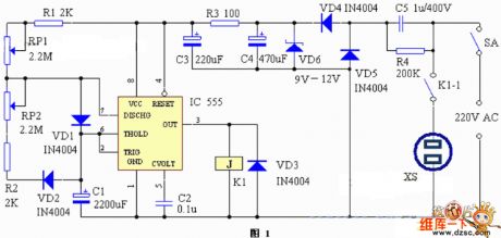
The repeated timing circuit is as shown in figure 1. The no steady-state circuit is composed of the IC555 RP1, R1, RP2, R2, VD1, VD2 and C1, the output port's (pin-3) high-to-low level conversion time is decided by the capacitor C1's charging-discharging time, and this is the opening and closing time of the electric appliance which is controlled by the circuit. This shows that we just need to adjust C1's charging-discharging time, so we can adjust the opening and closing time of the electric appliance which is controlled by the circuit. In this circuit, we can add the diodes VD1 and VD2 to ensure the C1's charging time and discharging time can be adjusted.
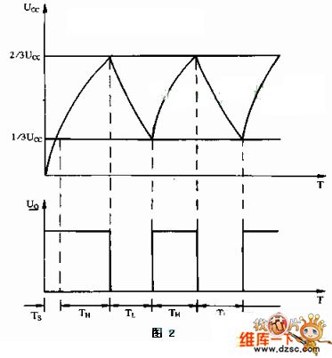
In this circuit's working process, pin-2 and pin-3's voltage changing process is as shown in figure 2. TH is the working time of the controlled electric appliance, TL is the rest time of the electric appliance.
Component selection:
In this circuit, the IC can chooses the time-base circuit such as the LM555, NE555, MA555 and 5C1555; relay K1 can choose the small and medium-size power relay with the Rated working voltage of 9V to 12V; the diode VD6 can choose the diode with 12V voltage value such as 2DW21.etc.
Reprinted Url Of This Article:
http://www.seekic.com/circuit_diagram/Automotive_Circuit/repeated_timing_circuit.html
Print this Page | Comments | Reading(3)

Article Categories
power supply circuit
Amplifier Circuit
Basic Circuit
LED and Light Circuit
Sensor Circuit
Signal Processing
Electrical Equipment Circuit
Control Circuit
Remote Control Circuit
A/D-D/A Converter Circuit
Audio Circuit
Measuring and Test Circuit
Communication Circuit
Computer-Related Circuit
555 Circuit
Automotive Circuit
Repairing Circuit
Code: