Position: Home > Circuit Diagram > Automotive Circuit > LTC1043 frequency control gain amplifier circuit
Automotive Circuit
LTC1043 frequency control gain amplifier circuit
Published:2011/6/20 5:34:00 Author:John | Keyword: gain amplifier | From:SeekIC

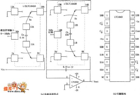
The figure shows gain amplifier circuit controlled by frequency. Different input clock frequencies are used to control the amplifier’s gain circuit, thus being called the frequency gain control circuit. Figure (a) shows that the circuit consists of two parts: analog switch and integrated amplifier. Analog switch consists of two pieces of precision capacitor switches LTC1043 and integrated amplifier uses the JFET input type op-amp LT1056.
Reprinted Url Of This Article:
http://www.seekic.com/circuit_diagram/Automotive_Circuit/LTC1043_frequency_control_gain_amplifier_circuit.html
Print this Page | Comments | Reading(3)

Article Categories
power supply circuit
Amplifier Circuit
Basic Circuit
LED and Light Circuit
Sensor Circuit
Signal Processing
Electrical Equipment Circuit
Control Circuit
Remote Control Circuit
A/D-D/A Converter Circuit
Audio Circuit
Measuring and Test Circuit
Communication Circuit
Computer-Related Circuit
555 Circuit
Automotive Circuit
Repairing Circuit
Code: