Automotive Circuit
Reader and transponder 2ASK modem circuit
Published:2011/6/19 23:54:00 Author:John | Keyword: modem, Reader, transponder | From:SeekIC

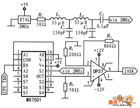
2ASK’s carrier signal is 2MHz sine wave. It achieves crystal of the square wave through a low pass filter. Digital modulation signal is output from the CPU's serial port and the signals are controlled to on or off through the analog switch MX7501, resulting in 2ASK signals. L1, L2, C1 and C2 constitute the second-order Butterworth low-pass filter, whose output is approximately sine wave’s 2 MHz signals. R1 and R4 lead to the matching of the LC filter impedance. When EN is 0, the OUT is 0; vice versa for the S1 channel signal. The following figure shows the reader’s 2ASK modulation circuit.
Reprinted Url Of This Article:
http://www.seekic.com/circuit_diagram/Automotive_Circuit/Reader_and_transponder_2ASK_modem_circuit.html
Print this Page | Comments | Reading(3)

Article Categories
power supply circuit
Amplifier Circuit
Basic Circuit
LED and Light Circuit
Sensor Circuit
Signal Processing
Electrical Equipment Circuit
Control Circuit
Remote Control Circuit
A/D-D/A Converter Circuit
Audio Circuit
Measuring and Test Circuit
Communication Circuit
Computer-Related Circuit
555 Circuit
Automotive Circuit
Repairing Circuit
Code: