Automotive Circuit
RC bridge oscillator circuit
Published:2011/6/4 12:36:00 Author:John | Keyword: RC bridge oscillator | From:SeekIC

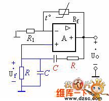
RC bridge oscillator circuit is just as shown in the figure. RC series-parallel network is connected to the output end and inverting input end of op-amp, aiming to form a positive feedback network with a frequency selective function. Besides, Rf and R1 are set within the op-amp's input end and its inverting input end. An integrated operational amplifier is connected with previous circuit to form a negative feedback amplifier circuit.
According to the following figure, the positive feedback circuit and negative feedback circuit form a Wien bridge circuit. And input and output terminals of the op-amp are connected across the bridge respectively. Therefore, this oscillation circuit is called RC bridge oscillator circuit.
Reprinted Url Of This Article:
http://www.seekic.com/circuit_diagram/Automotive_Circuit/RC_bridge_oscillator_circuit.html
Print this Page | Comments | Reading(3)

Article Categories
power supply circuit
Amplifier Circuit
Basic Circuit
LED and Light Circuit
Sensor Circuit
Signal Processing
Electrical Equipment Circuit
Control Circuit
Remote Control Circuit
A/D-D/A Converter Circuit
Audio Circuit
Measuring and Test Circuit
Communication Circuit
Computer-Related Circuit
555 Circuit
Automotive Circuit
Repairing Circuit
Code: