
Automotive Circuit
Index 29
ZERO_POWER_ENGINE_TACHOMETER
Published:2009/7/16 3:22:00 Author:Jessie
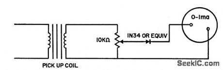
Requires no battery or other power source. Coil from 10 K relay serves as pickup for mounting near rotating magnets of flywheel of outboard motor or magneto. When rotating magnets are not available, as in most automotive engines, variable-reluctance pickup is used. This can be mode from old loudspeaker, mounted so fan blades of generator pass between pickup coil and permanent magnet. Coil mounting should be aluminum to maintain calibration that is made with commercial tachometer.-K. M. Bronscome, Engine Tachometer, EEE, 10:9,p 27. (View)
View full Circuit Diagram | Comments | Reading(626)
PASSIVE_TACHOMETER
Published:2009/7/16 3:21:00 Author:Jessie
Circuit is placed in series with ignition coil to pick up ignition pulses and feed them to integrating rate-meter calibrated in rpm. Number of pulses per shaft revolution depends on number of cylinders.-F.Trainor, Unique Engine Tachometer uses only Passive Components, Electronics, 35:30. P 40-41. (View)
View full Circuit Diagram | Comments | Reading(601)
STAIRCASE_INTEGRATOR_FOR_ROTATION_ANALYZER
Published:2009/7/16 3:19:00 Author:Jessie
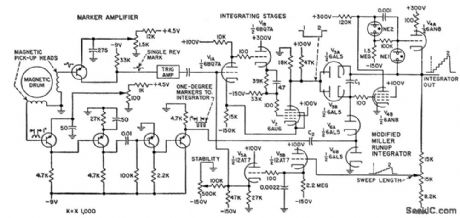
Used to observe relationship of crankshaft angle in gosoline engines to cylinder pressure and ignition timing. Parameters under study are indicated by angular displacement of rotating disk and are converted into signals for cro display. Magnetic drum is coupled to shaft under test. Ferrite-coated fiber disk with 1°magneticcdly recorded markers is source for pulses that are amplified for staircase integrating amplifier that feeds cro.-G. E. Edens, Stairstep Integrator Analyzes Rotation, Electronics, 31:13,p 41-43. (View)
View full Circuit Diagram | Comments | Reading(546)
FUEL_PUMP_OSCILLATOR
Published:2009/7/16 3:17:00 Author:Jessie

Silicon transistor serves as switch that eliminates arcing contacts, permitting use of pump in explosive atmosphere, even inside fuel tank. Power transistor is in blocking oscillator circuit for driving solenoid plunger assembly of commercial electric fuel pump. Feedback winding was added to drive coil. Ratio of solenoid coil turns to feedback turns should be 4 to 1 to insure proper starting in cold weather.-H. F. Weber, Transistor Operated Fuel Pump Eliminates Arcing Contacts and Commutator Brushes, Motorola Application Note AN-175, Feb. 1966. (View)
View full Circuit Diagram | Comments | Reading(990)
GATED_AMPLITUDE_RATIO_INDICATOR
Published:2009/7/16 3:16:00 Author:Jessie
Accurately measures cylinder gas temperature as function of engine-cycle phase angle, by using amplitude discriminator to indicate ratio of two infrared radiation intensities emitted by gas at two known wavelengths. Discrimination is accomplished by amplifying 0.1% slice of radiation signal.-R. R. Bockemuehl, Gated Ratio Indicator Aids Engine Research, Electronics, 32:13, p 64-65. (View)
View full Circuit Diagram | Comments | Reading(515)
HEADLIGHT_DIMMER
Published:2009/7/16 3:12:00 Author:Jessie
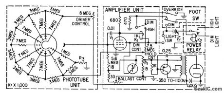
Will hold low beam setting even when approaching driver dims his headlights. Restores high beam only when light is completely removed from photocell. Street lights therefore keep system on a low beam. Used in Autronic Eye.-W. E. Bushor, Electronics and the American Automobile, Electronics, 31:47, p 73-79. (View)
View full Circuit Diagram | Comments | Reading(0)
SCS_SINGLE_PULSE_GENERATOR
Published:2009/7/16 3:11:00 Author:Jessie
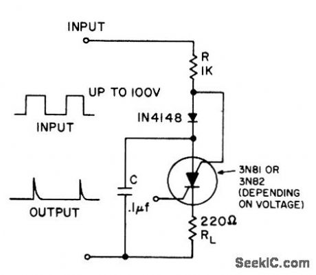
Gives one output pulse for each positive-going input. Can be used as tachometer, power loss detector, or peak detector.- Transistor Manual, Seventh Edition, General Electric Co., 1964, p 434. (View)
View full Circuit Diagram | Comments | Reading(700)
GAS_TUBE_AUTO_IGNITION
Published:2009/7/16 3:10:00 Author:Jessie
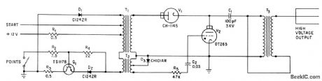
Thyratron V2 discharges C1 through spark coil T3 to provide ignition spark each time points open and magnetic field of trigger transformer T2 collapses. Field is built up in T1-T2 by power transistor Q1 when points close again,-H. P. Quinn, Gas Tubes and Transistor for Electronic Ignition, Electronics, 34:50, p 62-64. (View)
View full Circuit Diagram | Comments | Reading(1108)
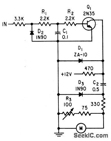
AUTOMATIC_IGNITION_ADVANCE
Published:2009/7/16 3:08:00 Author:Jessie
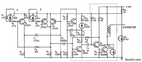
Inductive pickups on engine crankshaft feed to A and B, to make fining vary with engine speed by triggering monostable delay placed ahead of basic Delcotronic spark generator (dashed lines).-A. R. Hayes, Electronically Controlling Auto's Engine Spark,Electronics, 37:32, 43-44. (View)
View full Circuit Diagram | Comments | Reading(1115)
AUTO_TACHOMETER
Published:2009/7/16 3:06:00 Author:Jessie
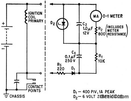
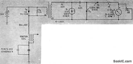
Connects to automobile circuit at battery and at distributor contact points.Zener diode D2 limits maximum charging voltage across C2.-J. A. Irvine, No Moving Parts in Auto Tachometer, Electronics, 39:9, p 77-78. (View)
View full Circuit Diagram | Comments | Reading(965)
AUDIBLE_TURN_SIGNAL_INDICATOR
Published:2009/7/16 3:05:00 Author:Jessie
Produces two different tones in synchronism with turn-signal flashers. Diodes prevent short-circuit. For autos with positive ground. - Transistor Manual, Seventh Edition, General Electric Co., 1964, p 381. (View)
View full Circuit Diagram | Comments | Reading(868)
INTERMITTENT_WINDSHIELD_CIRCUIT
Published:2009/7/13 5:12:00 Author:May
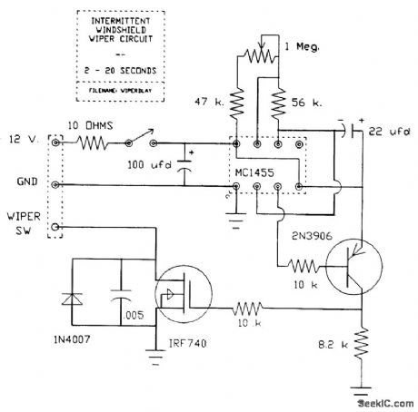
Basic timing is accomplished by the 555 IC. The resistor and capacitor network on pins 6, 7, and 8 sets the minimum delay at 2 s and the maximum at 20 s. The 555 output on pin 3 drives a 2N3906 PNP transistor to provide the proper input to the IRF740 power MOSFET. The MOSFET does the work and switches the wiper motor on at the end of the delay time. The wiper circuit uses a cam and switch arrangement on the drive assembly to cause the wiper blades to park in the proper place when the wipers are turned off. This cam switch is open when the blades are parked; the dashmounted wiper switch is in parallel with the cam switch. The intermittent circuit is wired to the cam switch as shown. When activated, and with the dash switch in the OFF position, the power MOSFET puts a ground on one side of the wiper motor, and the motor starts running. Shortly afterwards, the cam switch closes and forces the motor to continue running (regardless of the MOSFET's on/off status) until the PARK position is reached and the cam switch opens. The motor then stops, and one cycle is complete. (View)
View full Circuit Diagram | Comments | Reading(1715)
SINGLE_TRANSISTOR_AUTO_TACHOMETER
Published:2009/7/16 3:49:00 Author:Jessie
Uses zener diode to compensate for variations in 12-v supply. Meter is calibrated in rpm, using R3 for 0ncl adjustment. Range is 0 to 6,000 rpm. Input is ignition wave-form.-J. Cowan, Auto Tachometer Uses Transistor, Electronics, 31:33, p 92-94. (View)
View full Circuit Diagram | Comments | Reading(827)
HIGH_VOLTAGE_PULSE_GENERATOR
Published:2009/7/16 3:48:00 Author:Jessie

Square-wave input to transistor Q1 triggers scr on and off, inducing high-voltage damped-oscillation pulse in secondary of T1. Used for auto ignition and other applications requiring up to 30 kv from 0 to 400 times per second. -D. R. Grafham, Now the Gate Turnoff Switch Speeds Up D-C Switching, Electronics, 37:12, p 64-71. (View)
View full Circuit Diagram | Comments | Reading(3177)
400000_RPM_TACHOMETER_DISPLAY
Published:2009/7/16 3:46:00 Author:Jessie
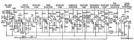
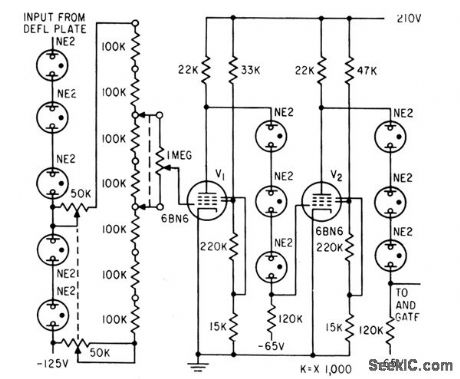
Has five Dekatron tubes arranged in cascade. Negative-going pulses from plate of gating tube are fed to 30-microsec one-shot mvbr V 10. Tetrode thyratron returns Dekatron to zero at end of counting period.-J. K. Goodwin, Digital Tachometer Aids in Turbine Design, Electronics, 32:15, p 58-61. (View)
View full Circuit Diagram | Comments | Reading(621)
TRANSISTOR_DECREASES_RESET_TIME
Published:2009/7/16 3:45:00 Author:Jessie
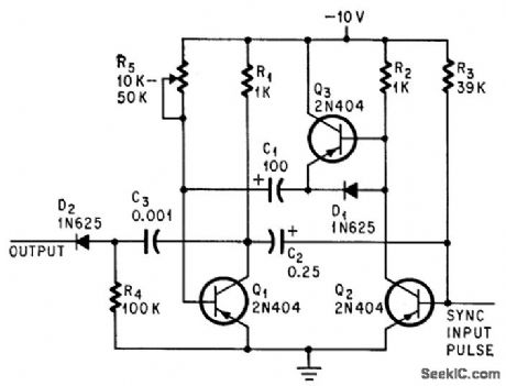
Time for recharging C1 is reduced by factor of 30 when Q3 is added to conventional astable mvbr.-S. A. Bell, Added Transistor Decreases Multivibrator Reset Time, Electronics, 37:21, p 72-73. (View)
View full Circuit Diagram | Comments | Reading(649)
LINE_TRIGGERED_SQUARE_WAVE_GENERATOR
Published:2009/7/16 3:44:00 Author:Jessie
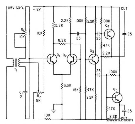
Bistable multivibrator Q1-Q2 is triggered by II through master phasing network R1-C1. R2 adjusts duty cycle. Output signal goes to frequency comparator that makes lab engine duplicate parameters recorded on magnetic tape during actual road run.-V. C. Vanderbilt and C. L. Zimmer, Magnetic Tape Recorder Programs Engine Dynamometer Tests, Electronics, 33:51, p 74-77. (View)
View full Circuit Diagram | Comments | Reading(533)
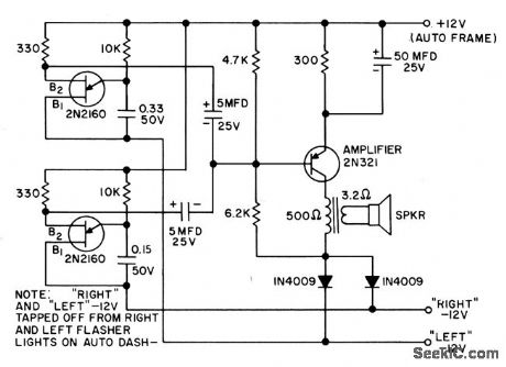
AUDIBLE_TURN_SIGNAL_INDICATOR_1
Published:2009/7/16 3:42:00 Author:Jessie
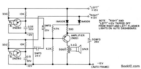
Produces two different tones in synchronism with turn-signal flashers.Diodes prevent short-circuit. For auto with negative ground.- Transistor Manual, Seventh Edition, General Electric Co,. 1964, p 381. (View)
View full Circuit Diagram | Comments | Reading(735)
QUICK_DISCONNECT_TACHOMETER
Published:2009/7/16 3:37:00 Author:Jessie
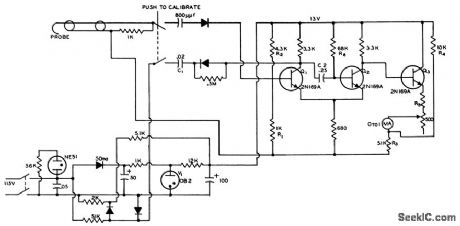
Can be connected and disconnected from engine fast enough for production-line speed adjustments. Pulse is picked up by curved probe that is hooked over ignition cable in use. Probe is made from RG58A/U coax with 1 inch of shield removed to provide coupling. Resulting pulse picked up is about 1 v, with width of about 20 microsec. Pulse is fed lo first stage Q1 of monostable mvbr, which acts on Q2 to give pulse with constant height and width, having engine spark frequency. Meter gets current pulse through emitter-follower for each spark, so average meter current is proportional to rpm.-Transistorized Tachometer, Electronic Circuit Design Handbook, Mactier Pub. Corp., N.Y., p 154. (View)
View full Circuit Diagram | Comments | Reading(752)
1_PPS_GATE_OPENING_TIMER
Published:2009/7/16 3:30:00 Author:Jessie
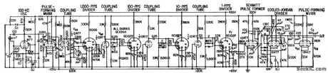
Produces pulses at 1-sec intervals to control gate of 400,000-rpm digital tachometer. Crystal oscillator produces 10-kc signal. Dekatrons are used to divide this to l-pps output.-J. K. Goodwin, Digital Tachometer Aids in Turbine Design, Electronics, 32:15, p 58-61. (View)
View full Circuit Diagram | Comments | Reading(620)
| Pages:29/164 At 202122232425262728293031323334353637383940Under 20 |
Circuit Categories
power supply circuit
Amplifier Circuit
Basic Circuit
LED and Light Circuit
Sensor Circuit
Signal Processing
Electrical Equipment Circuit
Control Circuit
Remote Control Circuit
A/D-D/A Converter Circuit
Audio Circuit
Measuring and Test Circuit
Communication Circuit
Computer-Related Circuit
555 Circuit
Automotive Circuit
Repairing Circuit