
Automotive Circuit
Index 31
The 3.0L engine CMP sensor, CKP sensor and ICM circuit of Shanghai GM Buick-MPV (GL8)
Published:2011/7/20 2:48:00 Author:Borg | Keyword: CMP sensor, CKP sensor, ICM circuit
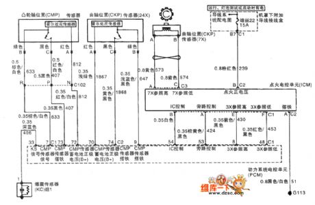
The 3.0L engine CMP sensor, CKP sensor and ICM circuit of Shanghai GM Buick-MPV (GL8)
(View)
View full Circuit Diagram | Comments | Reading(724)
The 2.5L(LBB) and 3.0L(LW9) engine circuit of Shanghai GM Buick-Regal (13)
Published:2011/7/20 2:14:00 Author:Borg | Keyword: engine circuit, Buick-Regal
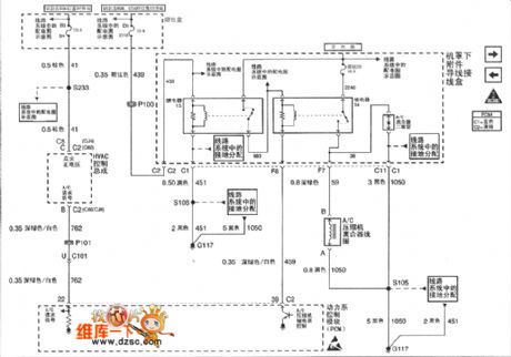
Figure 1. The 2.5L(LBB) and 3.0L(LW9) engine circuit of Shanghai GM Buick-Regal (13) (View)
View full Circuit Diagram | Comments | Reading(456)
The 2.5L(LBB) and 3.0L(LW9) engine circuit of Shanghai GM Buick-Regal (12)
Published:2011/7/20 2:15:00 Author:Borg | Keyword: engine circuit, Buick-Regal
Figure 1. The 2.5L(LBB) and 3.0L(LW9) engine circuit of Shanghai GM Buick-Regal (12) (View)
View full Circuit Diagram | Comments | Reading(378)
AC_MOTOR_CONTROL
Published:2009/7/20 2:29:00 Author:Jessie
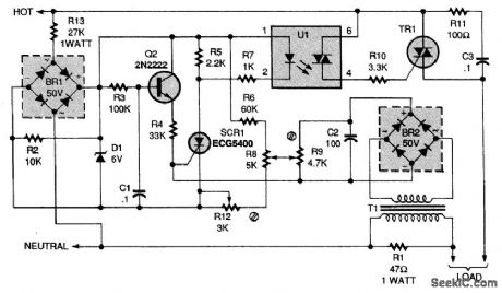
This circuit controls fans and other ac motors that have less than 1/4 horsepower and lack a centrifugal starting switch. It works by controlling the effective voltage in the ac circuit and governs both starting and varying load conditions. A ramg voltage is developed across capacitor C1. The voltage across C1 will vary the delay in turning on SCR1. The amplitude of that voltage is controlled manually by R8 for adjusting the motor speed, and by a preadjusted potentiometer (R9) to provide governing action (R9 should be adjusted to provide maximum regulation). The level of the ramp, relative to the firing voltage of Q1, is set by R12. The value of R1, must be chosen to accomrnodate the load; a lower value might be more satisfactory for a larger motor. Transformer T1 can be wound with a primary of 25 turns of 26-gauge wire and a secondary of 200 turns. Alternatively, any small transformer with a turns ratio of approximately 1:10 will do. (View)
View full Circuit Diagram | Comments | Reading(0)
SOLID_STATE_DRILL_SPEED_CONTROL
Published:2009/7/20 2:27:00 Author:Jessie
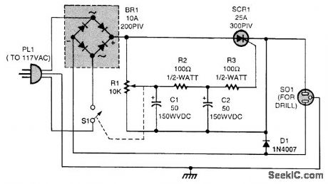
Add this circuit to a single-speed drill to make the speed variable. The bridge rectifier (BR1) provides the full-wave pulsing direct current for the SCR switc (SCR1); BR1 should be rated at 200 PIV and have a current rating of 10 A, while SCR1 should have a PIV of 300 V and a current rating of 25 A. Diode D1 is used to counter the back voltage developed by the drill motor; D1 can be rated at 2 A. The speed of the drill is varied by R1. (View)
View full Circuit Diagram | Comments | Reading(1143)
The ABS pulling over switch input and torque circuits of Buick-Regal
Published:2011/7/20 1:38:00 Author:Borg | Keyword: ABS, pulling over switch, Buick-Regal
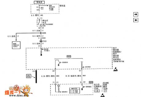
Figure 1. The ABS pulling over switch input and torque circuits of Shanghai GM Buick-Regal (View)
View full Circuit Diagram | Comments | Reading(436)
The ABS wheel rotating speed sensor and EBOM circuits of Buick-Regal
Published:2011/7/20 1:46:00 Author:Borg | Keyword: rotating speed sensor, Buick-Regal
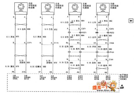
Figure 1. The ABS wheel rotating speed sensor and EBOM circuits of Shanghai GM Buick-Regal (View)
View full Circuit Diagram | Comments | Reading(593)
FAN_SPEED_CONTROLLER
Published:2009/7/20 2:19:00 Author:Jessie
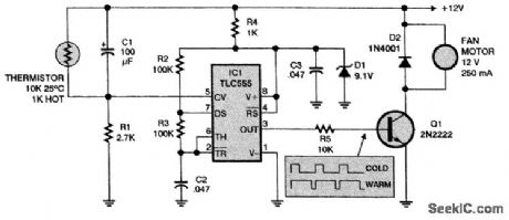
The speed of the fan motor increases as the thermistor gets warmer. The motor is fed with pulses whose duty cycle increases from 34 to 100 percent. (View)
View full Circuit Diagram | Comments | Reading(1033)
The ABS pulling over switch and torque circuit of Shanghai GM Buick-MPV (GL8)
Published:2011/7/20 1:53:00 Author:Borg | Keyword: ABS, pulling over switch, torque circuit
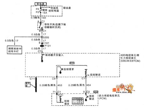
The ABS pulling over switch and torque circuit of Shanghai GM Buick-MPV (GL8)
(View)
View full Circuit Diagram | Comments | Reading(508)
The ABS wheel rotating speed sensor and EBCM/EBTCM circuit of Shanghai GM Buick-MPV (GL8)
Published:2011/7/20 1:56:00 Author:Borg | Keyword: ABS, wheel rotating speed sensor, EBCM/EBTCM
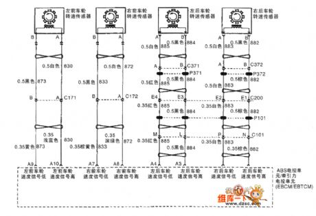
The ABS wheel rotating speed sensor and ABS electric/traction control unit circuit of Shanghai GM Buick-MPV (GL8)
(View)
View full Circuit Diagram | Comments | Reading(895)
The 2.5L(LBB) and 3.0L(LW9) engine circuit of Shanghai GM Buick-Regal (14)
Published:2011/7/20 2:14:00 Author:Borg | Keyword: engine circuit, Buick-Regal
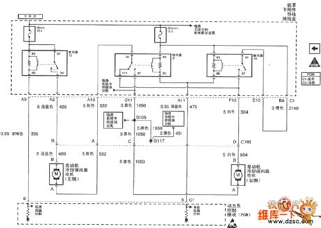
Figure 1. The 2.5L(LBB) and 3.0L(LW9) engine circuit of Shanghai GM Buick-Regal (14) (View)
View full Circuit Diagram | Comments | Reading(490)
MOTORCYCLE_INTERCOM
Published:2009/7/20 2:44:00 Author:Jessie
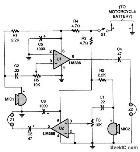
Why yell at your passenger when you can talk? Use this two-way intercom to make communicating on the open road a lot easier. (View)
View full Circuit Diagram | Comments | Reading(1864)
The car distance audio reminder (2)
Published:2011/7/22 6:46:00 Author:qqtang | Keyword: audio reminder
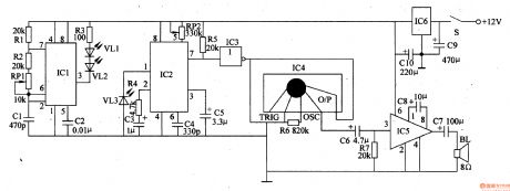
The working principle of the circuitThe car distance language reminder circuit consists of the power supply circuit, infrared emitter, infrared receiver and audio alarm circuit, see as figure 7-131.
The power supply circuit consists of ignite switch circuit, 3-phase regulated circuit IC6 and filter capacitors of C9 and C10. The infrared emitter consists of the relay R3, infrared LED of VL1 and VL2 and the 40khz multi-resonance oscillator circuit. The oscillator consists of the time-based integrated circuit IC1, resistors of R1 and R2, potentiometer RP1 and capacitors of C1 and C2 (View)
View full Circuit Diagram | Comments | Reading(449)
MOTORCYCLE_TURN_SIGNAL_SYSTEM
Published:2009/7/20 2:43:00 Author:Jessie
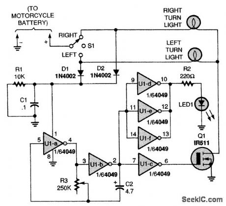
A low-frequency oscillator made up from a CMOS hex inverter drives an LED indicator and a power FET to act as a flasher. R3 and C2 control the flash rate. S1 controls L or R side lights for turnsignaling purposes. (View)
View full Circuit Diagram | Comments | Reading(0)
MOTORCYCLE_BURGLAR_ALARM
Published:2009/7/20 2:41:00 Author:Jessie
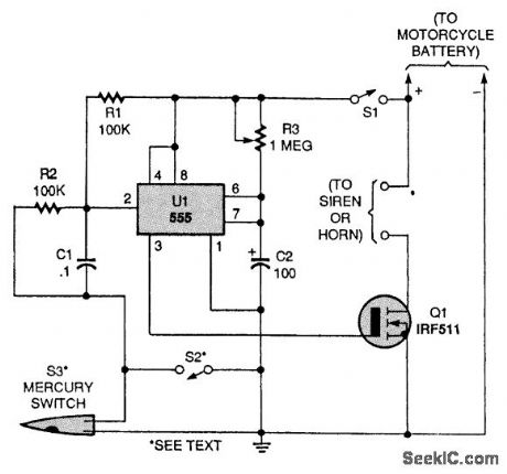
A 555 lC is connected in a one-shot timer circuit that turns on an FET and either a siren or the bike's horn for a preset time period. Switch S1 is used as an on/off switch. Closing either of two switches, S2 or S3, will trigger the IC. When either switch closes, pin 2 of U1 goes low. That triggers the IC to produce a positive output at pin 3 and sounds the alarm for the time period set by R3. The mercury switch, S3, is the switch that activates the alarm if someone moves your bike. Switch S2 can be used as a panic switch if you ever feel threatened. The IRF511 N-channel FET (Q1) will handle currents up to 4 A. If you need a higher-current device, an IRF530, which is rated at 14 A, can be substituted. (View)
View full Circuit Diagram | Comments | Reading(3550)
The car electric igniter (3)
Published:2011/7/21 21:27:00 Author:qqtang | Keyword: electric igniter
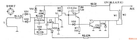
The working principle of the circuit The car electric igniter circuit consists of the synchronous pulse process amplifier, switch booster and feedback circuit, see as figure 7-134.
The synchronous pulse signal generator circuit consists of the signal rotor, electromagnet coil L, resistor R1-R5, resistors C1 and C2, diodes VD1-VD4, the regulated diode VS1 and transistor V1 The switch booster circuit consists of the transistors of V2 and V3, resistors of R6, R7 and R9, diode VD5, capacitors of C3 and C4, booster transformer T and so on. (View)
View full Circuit Diagram | Comments | Reading(1976)
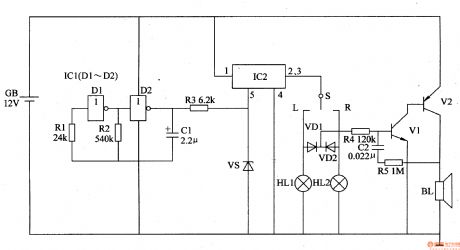
The automobile steering alarm (5)
Published:2011/7/22 21:50:00 Author:qqtang | Keyword: steering alarm

The working principle of the circuit The automobile steering alarm consists of the low-frequency oscillator, the electric switch circuit and the sound alarm circuit, see as figure 7-128.
The low-frequency oscillator consist of the NOR gate circuit ICl(Dl and D2), resistors of R1 and R2, capacitor C1 and so on. The electric switch circuit consists of the electric switch integrated circuit IC2, resistor and regulated diode VS. (View)
View full Circuit Diagram | Comments | Reading(418)
The automobile steering alarm (4)
Published:2011/7/22 21:39:00 Author:qqtang | Keyword: steering alarm
Here is to introduce an automobile steering alarm which can not only be the steering flash sound alarm, but also be the danger alarm.The working principle of the circuitThe automobile steering alarm consists of the low-frequency oscillator, electric switch circuit, control circuit, photoelectric display circuit and music alarm circuit and so on, see as figure 7-127.
The low frequency oscillator consists of the NAND circuits of D3 and D4 in the integrated circuit ICl(Dl-D4) and the external elements. (View)
View full Circuit Diagram | Comments | Reading(391)
The car electric igniter (2)
Published:2011/7/21 21:19:00 Author:qqtang | Keyword: electric igniter
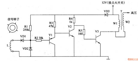
Here is to introduce the car electric igniter which is a contactless transistor igniter, the circuit is simple and easy to make.The principle of the circuitThe car electric igniter circuit consists of the pulse signal generator and switch booster circuit, see as figure 7-133.
The synchronous pulse signal generator circuit consists of the signal rotor (permanent magnet), electromagnet coil L and diode VD1 and VD2.The switch booster circuit consists of the transistor V1-V3, resistor R1-R5 and booster transformer T. (View)
View full Circuit Diagram | Comments | Reading(3412)
Meiri 3-Cylinder Engine Joint Electronic Control System Circuit
Published:2011/8/3 7:32:00 Author:Robert | Keyword: Meiri, 3-Cylinder, Engine, Joint, Electronic, Control, System
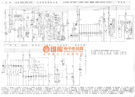
The picture shows the Meiri 3-cylinder engine joint electronic control system circuit.
In the circuit the part 1 is engine. The part 2 is battery. The part 3 is starting machine. The part 4 is ignition switch. The part 5 is speaker. The part 6 is cassette player. The part 7 is relay. The part 8 is electronic clock. The part 9 is oil pump. The part 10 is ECU. The part 11 is canister control valve. The part 12 is oil injector. The part 13 is hall sensor. The part 14 is stepper motor. The part 15 is thermistor. The part 16 is oxygen sensor. The part 17 is ignition coil. The part 18 is cooling fluid temperature sensor. The part 19 is vacuum sensor. The part 20 is throttle position sensor. The 21 is knock sensor. The part 22 is fault diagnosis interface. The part 23 is temperature control switch. The part 24 is fog lamp switch. And so on. (View)
View full Circuit Diagram | Comments | Reading(528)
| Pages:31/164 At 202122232425262728293031323334353637383940Under 20 |
Circuit Categories
power supply circuit
Amplifier Circuit
Basic Circuit
LED and Light Circuit
Sensor Circuit
Signal Processing
Electrical Equipment Circuit
Control Circuit
Remote Control Circuit
A/D-D/A Converter Circuit
Audio Circuit
Measuring and Test Circuit
Communication Circuit
Computer-Related Circuit
555 Circuit
Automotive Circuit
Repairing Circuit