
Automotive Circuit
Index 34
AUTORANGING
Published:2009/6/30 1:24:00 Author:May
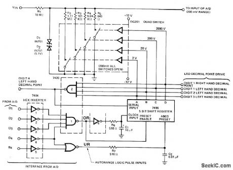
Digitally controlled attenuator uses DG201 quad analog switch as input ladder attenuator switches for A/D converter. Switches are controlled by digital logic that detects overrange and underrange information from A/D converter and closes appropriate attenuator path. Circuit is suitable for Siliconix LD110/111 or LD111/114 A/D converter,— Analog Switches and Their Applications, Siliconix、Santa Clara、CA、1976, p 6-28. (View)
View full Circuit Diagram | Comments | Reading(2120)
AUTOMATIC_SHUTOFF_1
Published:2009/6/29 22:41:00 Author:May
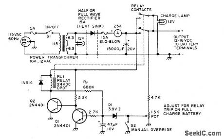
Charger automatically turns itself off when 12-V auto storage battery is fully charged. Setting of 1.5K pot determines battery voltage at which zener D1 conducts,turning on Q2 and pulling in relaythat disconnects charoer. If battery voltage drops below threshold, relay automatically connects charger again. S2 is dosed to bypass automatic control when charger itself is to be used as power supply.-G. Hinkle, The Smart Charger, 73 Magazine, Holiday issue 1976, p 110-111. (View)
View full Circuit Diagram | Comments | Reading(551)
Homemade audio remote control circuit
Published:2011/7/28 21:04:00 Author:John | Keyword: Homemade audio, remote control

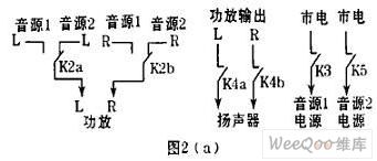

A remote control circuit has been designed for convenient use while manufacturing the sound by self. The easy purchased fan IC BA5104/BA8206 is used as the control chip. The functionality of the chip has been maximized through rational design. Due to the good performance, it can be well introduced for everyone. It can achieve the following functions: ① manual / remote control;② remote volume;③ source selection;④ delay shutdown;⑤ switch speaker protection;⑥ sound and light show. Transmitter circuit is shown in Figure 1. Receive and control circuits are shown in Figure 2. IC2 is the chip of the fan circuit.
(View)
View full Circuit Diagram | Comments | Reading(2338)
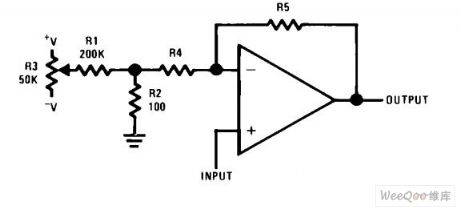
offset voltage adjustment differential amplifier circuit
Published:2011/7/28 20:50:00 Author:John | Keyword: offset voltage adjustment, differential amplifier

offset voltage adjustment differential amplifier circuit is shown.
(View)
View full Circuit Diagram | Comments | Reading(5680)
offset voltage adjustment non-inverting amplifier circuit
Published:2011/7/28 20:48:00 Author:John | Keyword: offset voltage adjustment, non-inverting amplifier
offset voltage adjustment non-inverting amplifier circuit is shown.
(View)
View full Circuit Diagram | Comments | Reading(3591)
AUTOMATIC_SHUTOFF
Published:2009/6/29 22:03:00 Author:May
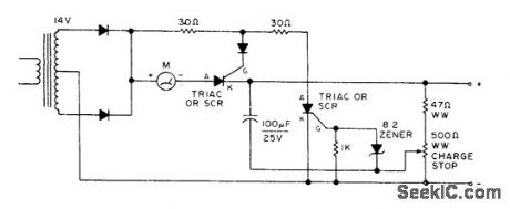
Prevents overcharging and dryout of battery under charge by shutting off automatically when battery reaches fullcharge voltage. Accepts wide range of batteries. Choose rectifying diodes and triacs or SCRs to handle maximum charging current desired. For initial adjustment, connect fully charged battery and adjust charge-stop pot until ammeter iust drops to zero.-Circuits, 73 Magazine, July 1977, p 34. (View)
View full Circuit Diagram | Comments | Reading(625)
SELF_CONTROLLED_AUTORANGING
Published:2009/6/29 21:50:00 Author:May
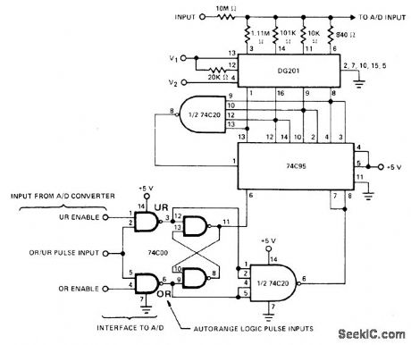
DG201 quad analog switch inserts one of four attenuator resistors in input circuit of Siliconix LD130 or comparable A/D converter under control of autoranging pulse output derived from converter. Control logic includes 74C00 quad twoinput NAND gate with two sections connected as flip-flop, 74C954-bit right-shift left-shift register, and 74C20 dual four-input NAND gate.— Analog Switches and Their Applications, Siliconix, Santa Clara, CA, 1976, p 6-28-6-29. (View)
View full Circuit Diagram | Comments | Reading(1299)
Integrated bias current compensation circuit
Published:2011/7/28 4:25:00 Author:John | Keyword: bias current

Integrated bias current compensation circuit is shown.
(View)
View full Circuit Diagram | Comments | Reading(587)
inverting summary amplifier circuit
Published:2011/7/28 4:20:00 Author:John | Keyword: inverting summary amplifier
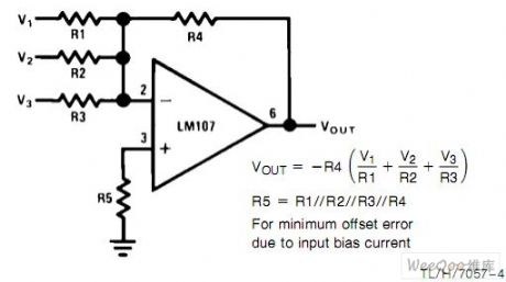
Inverting summary amplifier circuit is shown.
(View)
View full Circuit Diagram | Comments | Reading(458)
12_V_AUTOMATIC
Published:2009/6/29 21:29:00 Author:May

Circuit of Heathkit GP-21 automatic charger is self-controlling (Q1 and Q2) and provides protection against shorted or reversed battery leads (Q3 and Q4). Zener D8 is not standard value, so may be obtainable only in Heathkits. D1, D2, and D7 should all be on one heatsink.-H. Olson, Battery Chargers Exposed, 73 Magazine, Nov. 1976, p 98-100 and 102-104. (View)
View full Circuit Diagram | Comments | Reading(2644)
Toyota A340E S2 bit reverse oil circuit diagram
Published:2011/8/1 2:53:00 Author:Ecco | Keyword: Toyota , S2 bit, reverse oil

View full Circuit Diagram | Comments | Reading(1705)
TACHOMETER
Published:2009/6/28 23:40:00 Author:May

Intech/Function Modules A-8402 operating in frequency-to-vol tage converter mode serves as automotive tachometer having inherent linearity and ease of calibra-tion. Convener operates asynchronously, which does not affect accuracy when driving analog meter.-P. Pinter and D. Timm, Voltage-to-Frequency Converters-IC Versions Perform Accurate Data Conversion (and Much More) at Low Cost, EDNMagazine, Sept. 5, 1977, p 153-157. (View)
View full Circuit Diagram | Comments | Reading(0)
CAPACITOR_SERVES_AS_IGNITION_BATTERY
Published:2009/6/28 23:17:00 Author:May

Developed for use with capacitor-discharge ignition systems to provide independent voltage sourcefor ignition when starting car in very cold weather. Before attempting to start car, S1 is set to ON position for energizing DC-to-DC converter for charging C1 with DC voltage between 200 and 400 V. Starter is now engaged. If voltage of storage battery drops as starter slowly turns engine over, C1 still represents equivalent of fully charged 12-V storage battery that is ca pable of driving ignition system for almost a minute.-W. Stalzer, Capacitor Provides Artificial Battery for Ignition Systems, EDN Mage-zine, Nov. 15, 1972, p 48. (View)
View full Circuit Diagram | Comments | Reading(1078)
AUTO_TRAILER_INTERFACE_FOR_LIGHTS
Published:2009/6/28 23:13:00 Author:May


Low-cost transistors and two relays combine brake-light and tum-indicator signals on common bus to ensure that trailer lights respond to both commands. C1 and C2 charge to peak amplitude of tum signal, which flashes about 2 times per second. Values are selected to hold relay closed between flash intervals; if capacitance is too large, brake signal cannot immediately activate trailer lights after tum signal is canceled. Developed for new cars in which sep-arate turn and brake signals are required for safety.-M. E. Gilmore and C. W. Snipes, Dar-lington-Switched Relays Link Car and Trailer Signal Lights, Electronics, Aug. 18, 1971, p 116. (View)
View full Circuit Diagram | Comments | Reading(824)
OPTOELECTRONIC_IGNlTION
Published:2009/6/28 23:02:00 Author:May

Combination of Iow-cost point-source LED and high-sensitivity phototransistor forms optical sensor for posi-tion of cam in distributor, Technique eliminates problems created by timing drift and distribu-tor-shaft play. Sensor head is small enough to fit most distributors. Article gives dimensioned drawings for shutter design and sensor mount-ing, and describes operation of associated capacitor-discharge electronic ignition circuit in detail. Leads to sensor do not require shielding.-H. Maidment, Optical Sensor lgnition System, Wireless World, Nov.1975, p 533-537. (View)
View full Circuit Diagram | Comments | Reading(1368)
OIL_LEVEL_GAGE
Published:2009/6/28 22:55:00 Author:May

Permits checking crankcase oil Ievel from driver's seat. Sensor consists of light-conducting Plexiglas rod attached to dipstick, with lamp L1 at top of rod and phototransistor Q1 mounted at add-oil mark on dipstick, about 1/2 inch below bottom of rod. At normal oil level, oil attenuates light between a, and bottom end of rod, making phototransistor resistance high. Pushing test switch makes C1 charge and saturate Q2 long enough to activate UJT AF oscillator Q3 and give short tone verifying that lamp is not bumed out and gage is working. When oil is Iow, enough Iight reaches Q1 to keep O2 saturated after C1 charges, giving continuous tone as long as switch is pushed.-L. Svelund, Electronic Dipstick, EEE Magazine, Nov. 1970, p 101. (View)
View full Circuit Diagram | Comments | Reading(588)
AUDIBLE_TURN_SIGNAL
Published:2009/6/28 22:52:00 Author:May

Gives 3500-Hz audible tone each time turn-signal light flashes on, to warn driver that signal has not been turned off when making less than right-angle turns.Schematic shown is for 12-V negative-ground systems. For 6.V negative-ground systems, cut values of R1 and R2 about in half. For positiveground systems, reverse connections to diodes and Sonalert.R1 and R2 are 2.7K 0.5 VV. D1 and D2 can be any general-purpose small-current silicon diode. SA is Mallory SC1.5 Sonalert.-A. Goodwin, Turn Signal Reminder, 73 Magazine, Holiday issue 1976, p 166. (View)
View full Circuit Diagram | Comments | Reading(521)
RF_MAGNETOMETER
Published:2009/6/28 22:50:00 Author:May

Measu res RF radiation and current distribution for antennas, transmission lines, ground leads, building wiring, and shields. Can also be used as sensitive portable field-strength meter. Will indicate orientation of field. High-Q circuit is tunable from 1.8 to 150 MHz for indicating frequency of fields produced by RF harmonic, Applications inplude detecting reradiation from rain gutters, metal fencing, towers, and guy wires that are distorting antenna field pattems, and detecting radiation from ground leads, appliance power cords, and hidden building wiring. When used as probe, will accurately pinpoint leakage of RF energy from joints, holes, or slots in shielded enclosures. Operation is similar to absorption-type wavemeter, except that pickup coil is electrostatically shielded by slotted aluminum IF trans-former can to eliminate capacitive coupling. Inductor is wound on ferrite coil to give very high a as pickup element.-W. M. Scherer, An R. F.Magnetometer and Field Strength Meter, CQ, April 1971, p 16-20. (View)
View full Circuit Diagram | Comments | Reading(2047)
DISTRIBUTOR_POINT_TACHOMETER
Published:2009/6/28 22:48:00 Author:May

555 timer receives its input pulses from distributor points of car. When timer output (pin 3) is high, meter receives calibrated current throung R6. When IC times out, meter current stops for remainder of duty cycle. Integration of varoable duty cayle by meter movement serves to provide visible indication of engine speed.- Signestic Analog Data Manula, Signetics, Sunnyvale, CA, 1977, p 724-725. (View)
View full Circuit Diagram | Comments | Reading(931)
WIPER_CONTBOL
Published:2009/6/28 22:40:00 Author:May

Operates wipers automatically at intervals, as required for very light rain or mist. Changing 560K resistot to 500K pot in series with 100K fixed resistor gives variable control of interval.-Circuits, 73 Magazine, July 1977, p 34. (View)
View full Circuit Diagram | Comments | Reading(574)
| Pages:34/164 At 202122232425262728293031323334353637383940Under 20 |
Circuit Categories
power supply circuit
Amplifier Circuit
Basic Circuit
LED and Light Circuit
Sensor Circuit
Signal Processing
Electrical Equipment Circuit
Control Circuit
Remote Control Circuit
A/D-D/A Converter Circuit
Audio Circuit
Measuring and Test Circuit
Communication Circuit
Computer-Related Circuit
555 Circuit
Automotive Circuit
Repairing Circuit