
Automotive Circuit
Index 27
Superheterodyne Receiving Module RXB1
Published:2011/8/9 17:46:00 Author:Vicky | Keyword: Superheterodyne Receiving Module

RXB1 uses crystal frequency stabilization technology. It has relatively high frequency stability and uses RX3400 as the superheterodyne receptor. The receiving sensitiveness is high, the performance is stable, the current is low, the usage is easy, the size is small and it is cheap. The short antenna can be connected in the outside so that it is convenient to use. It can transmit direct current to the 2000BPS signal.
Product specification
Working voltage: DC 5V
Transmission rate: 2~4KBPS
Working mode: ASK (amplitude modulation)
Static current: 2~3mA (available to be connected to power-saving mode in the outside)
Receiving sensitiveness: -105dBm
Size of appearance: 43×12×5mm
Working temperature: -40℃~+70℃
Working frequency: 315 MHz; 433 MHz;
Output frequency stability: ±30PBM
Output signal: TTL electrical level
Ranking of pins: VSS、DATA、DATA、VDD VDD、VSS、VSS、ANT
Function of pins: GND: ground connection DATA: receiving data outputDATA: receiving data outputVDD : working power,DC 5V ; VDD: working power,DC 5V ; VSS: ground connectionVSS: ground connection ANT: antenna (View)
View full Circuit Diagram | Comments | Reading(693)
Superheterodyne Receiving Module RXB2
Published:2011/8/9 17:48:00 Author:Vicky | Keyword: Superheterodyne Receiving Module
Product specification
Working voltage: DC 5V ±10%
Transmission rate: 9.60KBPS
Working mode: ASK (amplitude modulation)
Static current: 4.6mA (it is available to be connected to power-saving mode in the outside and the start-up time is 250µs; the low-current shutdown mode is 50nA, which effectively saves power)
Receiving sensitiveness: -112dBm
Size of appearance: 43×12×5mm
Working temperature: -40℃~+85℃
Working frequency: 315MHZ~433.92MHZ
Output signal: TTL electrical level
Built-in -65dB RF image frequency rejection circuit
400KHz work bandwidth (the optimizing point of the image frequency rejection is 315/433/868MHz)
Integration of PPL built-in voltage-controlled oscillator (VOC) and loop filter
Selecting IF bandwidth by exterior filter
IF bandwidth is 150K, a refined receiving system from RF to number data output
Ranking of pins: GND、SHUT、DATA、VDD VDD、GND、GND、ANT
Function of pins: GND: ground connection SHUT: receiving data output/interface for connecting power-saving modeDATA: receiving data outputVDD : working power,DC 5V ; VDD: working power,DC 5V ; GND: ground connectionGND: ground connection ANT: antenna
(View)
View full Circuit Diagram | Comments | Reading(466)
SN75322 dual positive and gate TTL-MOS driver circuit
Published:2011/8/8 9:05:00 Author:Fiona | Keyword: dual positive and gate, driver circuit
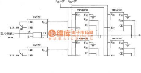
SN75322 is single dual positive and gate TTL-MOS driver circuit,which is used as an interface between TTL and high-voltage and high-current system.It uses TTL and MOS supply voltage,and can switch at a high speed.Its input is compatible with TTL and MOS circuits .It has a common strobe input. 5V power supply outputs are high impedance when vacancies. Output directly drives 4030 4K RAM,and needs two external PNP transistor while it is being used.The circuitthat SN75322 is used as a 4030MOS memory driver is shown as above.
(View)
View full Circuit Diagram | Comments | Reading(817)
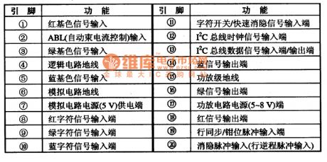
The pin function circuit of TDA9210 integrated circuit
Published:2011/8/8 9:03:00 Author:Fiona | Keyword: pin function, integrated circuit
1. pin function
TDA9210 integrated circuit uses 20-pin biserial inline package , and its pin functions are listed in Table 70.
(View)
View full Circuit Diagram | Comments | Reading(528)
TDA9321 Integrated circuit pin functions and data circuit
Published:2011/8/8 9:01:00 Author:Fiona | Keyword: pin functions and data
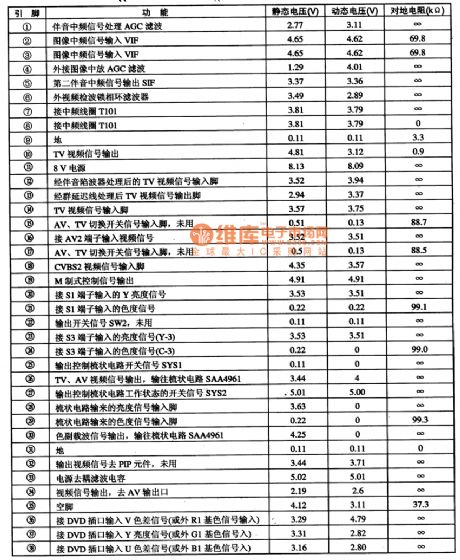
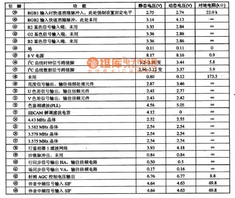
TDA9321 ——Intermediate frequency signal processing, field trip small signal processing, light-coloredhandle monolithic IC.TDA9321 is a small TV signal processing integrated circuit chip produced by PHLIPS, which is widely used in large-screen TV in the new multiplier, such as Changhong TD2000.1.FeaturesTDA9321 Integrated circuit contains image and sound IF circuit, small field scanning line signal processing circuit, luminanceand chrominance signal processing circuit, and other auxiliary functions circuit. The entire circuit completes the processing under I (2) C bus’s control.2.The whole pin functions and data TDA9321 IC uses 64-pin dual in-line package,which is applyed to Changhong color TV on the DT2000 frequency.And the integrated circuit ‘s pin functions are listed inTable 73.
(View)
View full Circuit Diagram | Comments | Reading(539)
ZhongHua saloon car engine circuit 1
Published:2011/8/8 2:14:00 Author:TaoXi | Keyword: ZhongHua, saloon car, engine circuit

F54-ABS fuse (60A) F55-storage battery fuse (70A) F56-ignition fuse (60A) F60-start fuse (60A) R35-start relay H03-power connector U01UA-connection point, in the ABS wiring harness U02A1A-connection point, in the engine room left wiring harness U05PA/U14PA/U16PA/U17PA-connection points, in the dashboard wiring harness T1-connector of engine left wiring harness and dashboard wiring harness T13-ABS wiring harness and engine room left wiring harness connector T15-dashboard wiring harness and engine room left wiring harness connector T47-interface of engine room left wiring harness and power connector (View)
View full Circuit Diagram | Comments | Reading(627)
ZhongHua saloon car engine circuit 3
Published:2011/8/8 2:00:00 Author:TaoXi | Keyword: ZhongHua, saloon car, engine
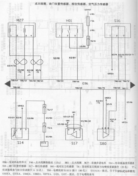
ZhongHua saloon car engine circuit
E06-Engine electronic control unit F46-ignition coil fuse(15A) H01-ignition coil M27-idle speed stepper motor S14-cooling fluid temperature sensor S16-throttle position sensor S17-phase sensor S80-absolute pressure sensor T6-engine room left wiring harness and EFI wiring harness connector T7-dashboard wiring harness and combination meter interface T80-EFI wiring harness and ECU interface U11A1A-connection point, in the left wiring harness of the engine U02EA,U03EA,U04EA,U06EA,U07EA,UOX,UOY-connection points, in the EFI wire harness (View)
View full Circuit Diagram | Comments | Reading(545)
ZhongHua saloon car ABS circuit 1
Published:2011/8/8 1:45:00 Author:TaoXi | Keyword: ZhongHua, saloon car, ABS
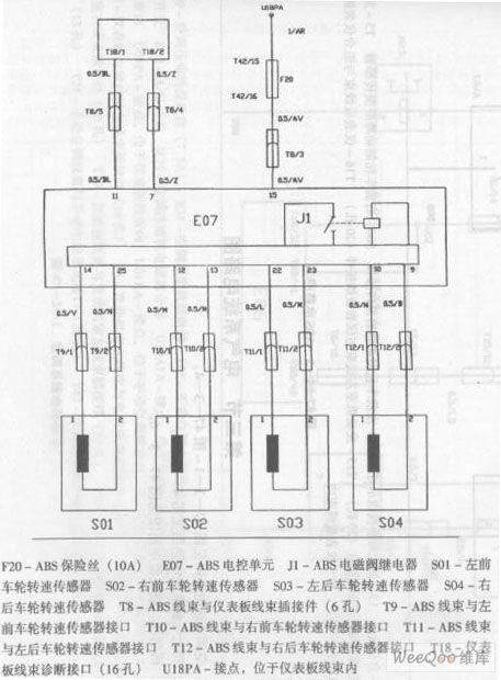
F20-ABS fuse(10A) E07-ABS electronic control unit J1-ABS electromagnetic valve relay S01-left front wheel revolution speed transducer S02-right front wheel revolution speed transducer S03-left rear wheel revolution speed transducer S04-right rear wheel revolution speed transducer T8-ABS wiring harness and dashboard wiring harness connector T9-ABS wiring harness and left front wheel revolution speed transducer interface T10-ABS wiring harness and right front wheel revolution speed transducer interface T11-ABS wiring harness and left rear wheel revolution speed transducer interface T12-ABS wiring harness and right rear wheel revolution speed transducer interface T18-dashboard wiring harness diagnosis interface U18PA-connection point of the dashboard wiring harness. (View)
View full Circuit Diagram | Comments | Reading(559)
The car electric igniter (4)
Published:2011/8/3 22:33:00 Author:qqtang | Keyword: electric igniter
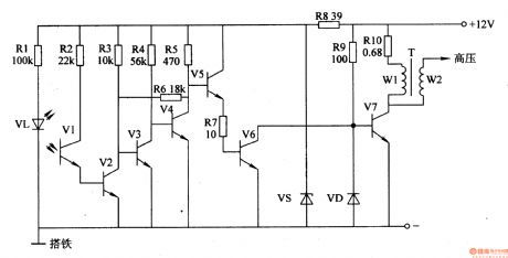
Here is to introduce the car electric igniter which adopts the photoelectric triggering method, and its feature is that neither of the trigger signal nor the closing angle is affected by the engine rotating speed.
The working principle of the circuit The car electric igniter circuit consists of the photoelectric trigger, amplifier circuit and switch booster circuit, see as figure 7-135.
The photoelectric trigger consists of the blanking disc (located between VL and VI, not in the figure), resistors of R1 and R2, infrared LED VL, infrared light sensitive transistor V1 and so on. The amplifier circuit consists of the transistor V2-V5, regulated diode VS and resistor R3-R6 and R8. (View)
View full Circuit Diagram | Comments | Reading(1043)
The car electric igniter (1)
Published:2011/8/3 23:04:00 Author:qqtang | Keyword: electric igniter
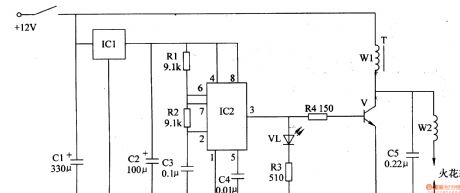
The principle of the circuit
The car electric igniter consists of the voltage stabilizing filter circuit, astable multi-resonance oscillator and booster circuit, see as figure 7-132.
The voltage stabilizing filter circuit consists of the filter capacitors of C1 and C2 and 3-terminal regulated circuit IC1. The astable multi-resonance oscillator consists of the resistors of R1 and R2, capacitors of C3 and C3, time-based integrated circuit IC2 and so on. The booster circuit consists of the LED VL, resistors R3 and R4, transistor V, booster transformer T and discharge capacitor C5. (View)
View full Circuit Diagram | Comments | Reading(690)
The car distance audio reminder (1)
Published:2011/8/3 23:15:00 Author:qqtang | Keyword: car distance, audio reminder
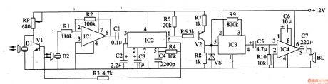
The working principle of the circuit The car distance language reminder circuit consists of the ultra-sonic emitter circuit, ultra-sonic receiver circuit, PLL circuit and audio reminding circuit, etc, see as figure 7-130.
The ultra-sonic emitter circuit consists of the ultra-sonic emitter B1, transistors of V1 and IC2, etc. The ultra-sonic receiver circuit consists of the ultra-sonic receiver B2, op-amp integrated circuit IC1 and external elements. The PLL circuit consists of IC2 and external elements. The audio indicating circuit consists of the transistor V2, language integrated circuit IC3, audio power amplifier integrated circuit IC4 and external elements. (View)
View full Circuit Diagram | Comments | Reading(575)
The automobile steering alarm (3)
Published:2011/7/29 4:35:00 Author:qqtang | Keyword: steering alarm
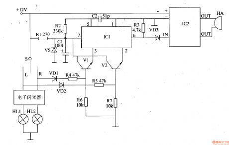
The working principle of the circuitThe automobile steering alarm consists of the regulated circuit, trigger circuit, audio circuit and audio output circuit, see as figure 7-126.
The regulated circuit consists resistor R1, regulated diode VS and filter capacitor C1. The trigger circuit consists of the diodes of VD1 and VD2, resistors R4-R7 and transistors of V1 and V2. The voice circuit consists of the voice integrated circuit IC1, resistor R2 and capacitor C2.The audio output circuit consists of the resistor R3, diode VD3, power amplifier circuit IC2 and ultra loud buzzer HA. (View)
View full Circuit Diagram | Comments | Reading(517)
The ultra-sonic safety alarm of car travelling
Published:2011/8/3 23:19:00 Author:qqtang | Keyword: ultra-sonic safety alarm, car travelling
The working principle of the circuitThe ultra-sonic safety alarm circuit of car travelling consists of the ultra-sonic wave detector, PLL audio decoder, trigger audio circuit and audio amplifier output circuit, see as figure 7-129.
The ultra-sonic wave detector consists of the the ultra-sonic wave emitter B1, ultra-sonic wave receiver B2, transistor V1, resistors of R1 and Rll-Rl9, potentiometer RP, capacitors C9-Cl2 and the op-amp integrated circuit lC4(Nl-N3). The PLL audio decoder consists of the audio decoder circuit IC1, resistor R2 and capacitors C1-C3. The trigger language integrated circuit consists of the resistors R3-R7, capacitor C4, transistor V2 and audio integrated circuit IC2. (View)
View full Circuit Diagram | Comments | Reading(422)
Golf Bora Comfort System Circuit
Published:2011/7/15 8:34:00 Author:Robert | Keyword: Golf, Bora, Comfort, System
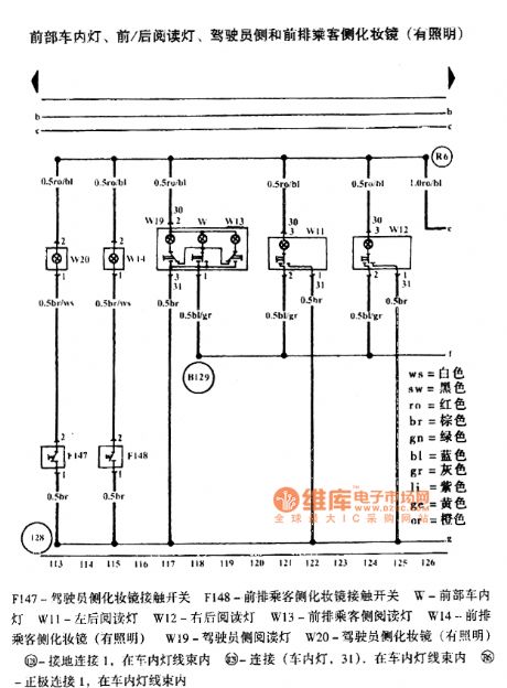
The pictures show the Golf Bora comfort system circuit.
The first picture shows the driver's side door electronic control unit, driver's side door window lifter, car inner lock switch, window lifter switch, rear door window lifter chain switch.
The second picture shows the driver's side door electronic control unit, driver's side central door clock, central door clock indicator lamp, left door warning lamp.
The third picture shows the driver's side door electronic control unit, rearview mirror adjustment switch, car external rearview mirror heating switch, rearview mirror folding switch.
The fourth picture shows the driver's side door electronic control unit, driver's side door electrical adjustable rearview mirror.
The fifth picture shows the front passenger side door electronic control unit, front passenger side door window lister, front passenger side central door lock.
The sixth picture shows the front passenger side door electronic control unit, front passenger side door external rearview mirror (electrical adjustment), right car door warning light.
And so on. (View)
View full Circuit Diagram | Comments | Reading(873)
Audi A4 1.8T Engine Circuit
Published:2011/8/2 21:57:00 Author:Robert | Keyword: Audi, A4, 1.8T, Engine
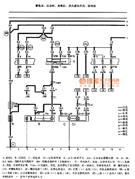


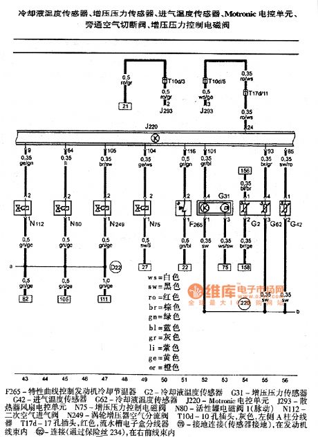

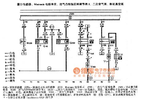

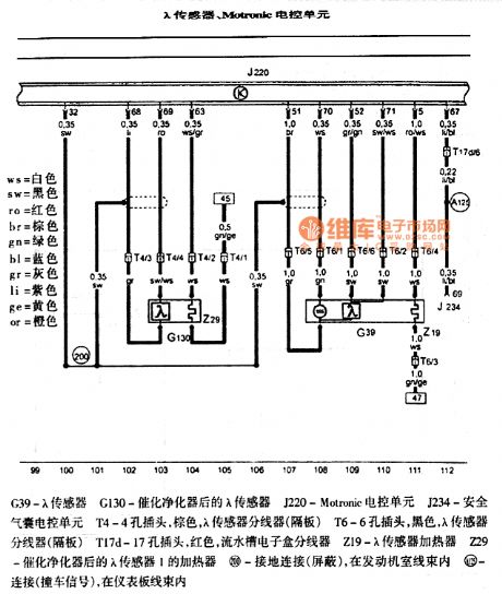
The pictures show the Audi A4 1.8T engine circuits.
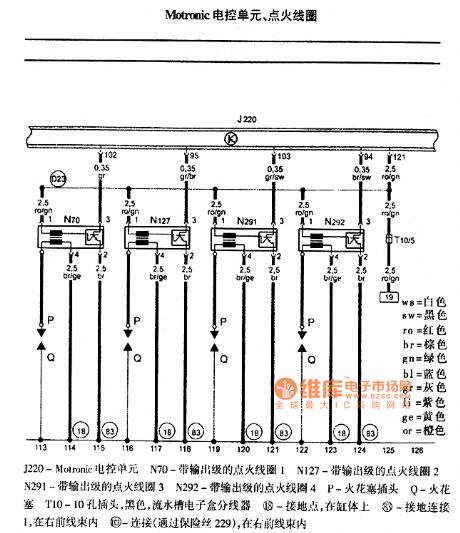
The first picture shows the battery, starting machine, generator, ignition starting switch, fuse.The second picture shows the fuel pump relay, Metronic ECU, Motronic power supply relay, fuse.The third picture shows the air flow meter, radiator exit cooling fluid temperature sensor, Motronic ECU, fuel injection pump.The fourth picture shows the cooling fluid temperature sensor, boost pressure sensor, intake air temperature sensor, Motronic ECU, bypass air shut-off valve, boost pressure control solenoid valve.The fifth picture shows the engine speed sensor, knock sensor 1, knock sensor 2, Motronic ECU.The sixth picture shows the hall sensor, Motronic ECU, admission camshaft correct timing adjustment valve 1, secondary air pump, brake vacuum pump.The seventh picture shows the accelerator pedal position sensor, Motronic ECU, throttle ECU.The eighth picture shows the λ sensor, Motronic ECU.The ninth picture shows the Motronic ECU and ignition coil. (View)
View full Circuit Diagram | Comments | Reading(3172)
Automotive Fuel Monitor Four
Published:2011/7/27 6:42:00 Author:Felicity | Keyword: Automotive Fuel Monitor

The circuit consists of fuel level monitoring circuit and alarm circuit. (It is showed in picture 7-61.)
Fuel level monitoring circuit consists of ignition switch S1, gasoline-type table and float sensor potentiometer.
Alarm circuit consists of alarm HA, LED HL, resistors Rl-R3, transistor Vl, V2, switch S2 and the relay K.
This monitor can warn the driver to refuel while the car is going to run out of fuel.
This automotive fuel monitor circuit consists of oil level detect circuit and alarm circuit ,as showed in the figure above.
When the oil level is higher than the lowest level , the float sensor in the high impedance state,and V1 and V2 both cut off, HA is noiseless and HL is off.
When the fuel is little and the oil lever is below the loweset level, the resistance of the float sesor drops to make V1 and V2 on. And K turns on, and the normally open contact of K closes; HA sends out alarm and HL lights up. (View)
View full Circuit Diagram | Comments | Reading(1465)
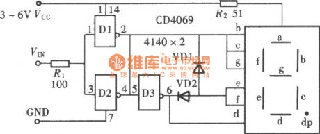
The Circuit Diagram of Text-display Logic-pen Consists of Gate Circuit (CD406) 3rd
Published:2011/8/8 21:46:00 Author:Felicity | Keyword: Text-display, Logic-pen
The circuitof text-display logic-pen consists of gate circuit (CD406) 3rd is shown in this figure (View)
View full Circuit Diagram | Comments | Reading(862)
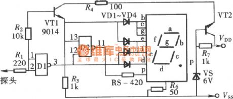
The Circuit Diagram of Text-display Logic-pen Consists of Gate Circuit (CD4011) 2nd
Published:2011/8/8 21:47:00 Author:Felicity | Keyword: Text-display, Logic-pen
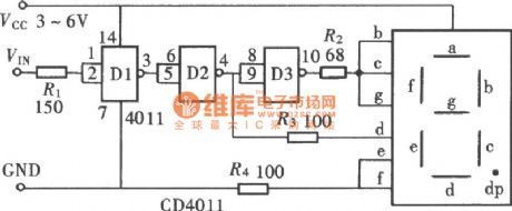
Text-display logic-pen consists of gate circuit has several forms. It can be consist of inverters or NOT-AND gates or NOR gates.The logic-pen shown in this figure consists of NOT-AND gate CD4011 and common anode nixie tube.
(View)
View full Circuit Diagram | Comments | Reading(1508)
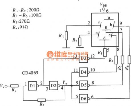
The Circuit Diagram of Text-display Logic-pen Consists of Gate Circuit (CD4069) 1st
Published:2011/8/8 21:47:00 Author:Felicity | Keyword: Text-display, Logic-pen
The figure shows the Circuit Diagram of the text-display logic-pen. The text here does not refer to “gao” and “di” in Chinese. It’s H and L, initial letters of High and Low. And it’s easy to use LED to comprise this pen, beacause the shape of this two letters corresponds to the LED circuit. (View)
View full Circuit Diagram | Comments | Reading(779)
The circuit diagram of a logic-pen that can shows the open state 2nd
Published:2011/8/8 21:47:00 Author:Felicity | Keyword: logic-pen, open state
The circuit diagram of a logic-pen that can shows the open state 2nd is shown above. (View)
View full Circuit Diagram | Comments | Reading(446)
| Pages:27/164 At 202122232425262728293031323334353637383940Under 20 |
Circuit Categories
power supply circuit
Amplifier Circuit
Basic Circuit
LED and Light Circuit
Sensor Circuit
Signal Processing
Electrical Equipment Circuit
Control Circuit
Remote Control Circuit
A/D-D/A Converter Circuit
Audio Circuit
Measuring and Test Circuit
Communication Circuit
Computer-Related Circuit
555 Circuit
Automotive Circuit
Repairing Circuit