
Automotive Circuit
Index 33
Mitsubishi Pajero light off-road vehicle front and rear window wiper washing wiring circuit diagram
Published:2011/5/10 0:59:00 Author:Rebekka | Keyword: Mitsubishi Pajero, light off-road vehicle , front and rear window

Mitsubishi Pajero lightoff-road vehicle before and after the window wiper washing wiring circuit diagram is shown as above. (View)
View full Circuit Diagram | Comments | Reading(638)
Mitsubishi Pajero light off-road vehicle electric control rearview mirror and cigarette lighter principle circuit
Published:2011/5/10 0:57:00 Author:Rebekka | Keyword: Mitsubishi Pajero , light off-road vehicle, electric control rearview mirror , cigarette lighter

Mitsubishi Pajero(PAJERO) light off-road vehicle electric control rearview mirror and cigarette lighter principle circuit .
68 fire switch; 108 rear view mirror remote control switch; 109,110 left rear view mirror remote control motivation; 111,112 right rear view mirror remote control motor; 113 cigar lighter. (View)
View full Circuit Diagram | Comments | Reading(710)
Shanghai GM Sail Engine Circuit
Published:2011/7/29 19:41:00 Author:Robert | Keyword: Shanghai, GM, Sail, Engine
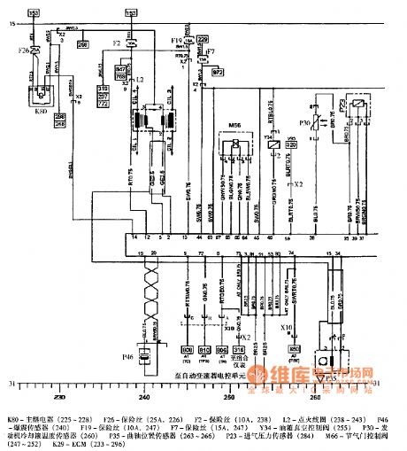
The picture shows the Shanghai GM sail engine circuit.
In the circuit, the K80 is the main relay (225-228). The F126 is fuse (25A, 226). The F2 is fuse (10A, 238). The L2 is ignition coil (238-243). The F46 is knock sensor (240). The F19 is fuse (10A, 247). The F7 is fuse (15A, 247). The Y34 is oil box vacuum control valve (255). The P30is engine cooling fluid temperature sensor (260). The P35 is crankshaft position sensor (263-266). The P23 is intake air pressure sensor (284). The M66 is throttle control valve (247-252). The K29 is ECM (233-296). (View)
View full Circuit Diagram | Comments | Reading(577)
Cheetah SUV ABS Circuit
Published:2011/8/1 10:45:00 Author:Robert | Keyword: Cheetah, SUV, ABS


The pictures show the Cheetah SUV ABS circuits.
In the first picture the part 1 is IOD connector. The part 2 is fuse. The part 3 is ignition switch (IG2). The part 4 is ignition switch (IG1). The part 5 is connected to charging and ignition system. The part 6 is connected to the clock, multi-function meter. The part 7 is connected to active traction 4WD system and the remote-control variable shock absorber. The part 8 is instrument cluster. The part 9 is connected to the constant speed control system. The part 10 is standby power. The part 11 is connected to brake alarm lamp, meter, light monitor, ignition key not pulling reminder, seat belt alarm lamp. The part 12 is connected to the ABS ECU. And so on. (View)
View full Circuit Diagram | Comments | Reading(531)
Santana 2000 Series M1.5.4 Engine Circuit
Published:2011/8/2 2:53:00 Author:Robert | Keyword: Santana, M1.5.4, Engine

The picture shows the Santana 2000 series M1.5.4 engine circuit.
In the picture the part 1 is engine ECU. The part 2 is fuel pump relay. The part 3 is ECU fuse. The part 4 is hall sensor. The part 5 is intake air pressure sensor. The part 6 is throttle position sensor. The part 7 is knock sensor. The part 8 is oxygen sensor. The part 9 is cooling fluid temperature sensor. The part 10 is oxygen sensor heater fuse. The part 11 is ignition coil. The part 12 is injector. The part 13 is idle speed regulator. The part 14 is used to adjust the idle speed, ignition advance angle and then it is connected to the ground. The part 15 is fault diagnosis device and it is connected to ground. The part 16 is electric fuel pump. The part 17 is fuel pump fuse. (View)
View full Circuit Diagram | Comments | Reading(1354)
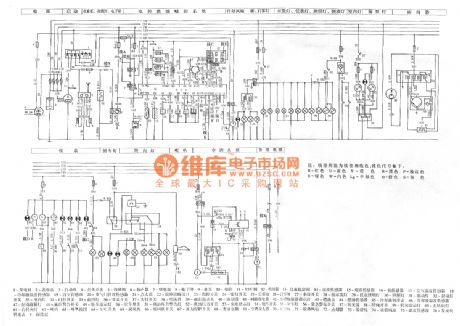
Audi A4 3.0L Engine Circuit
Published:2011/8/2 6:22:00 Author:Robert | Keyword: Audi, A4, 3.0L, Engine
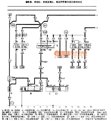
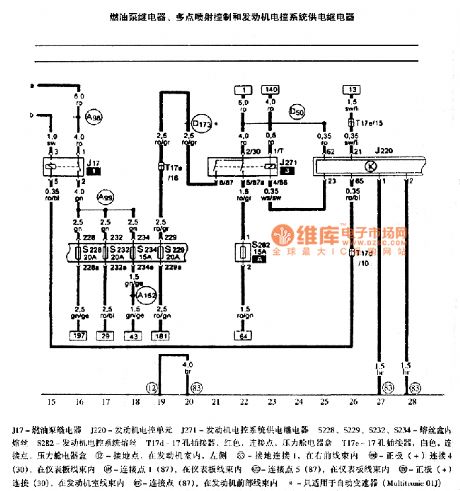
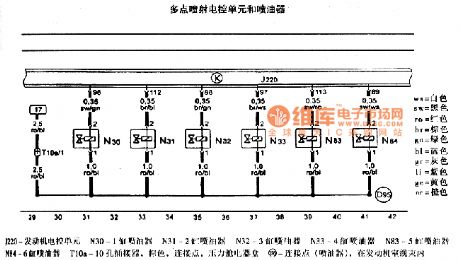
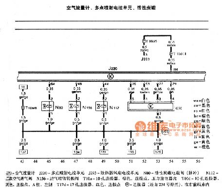

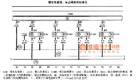
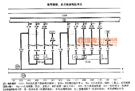
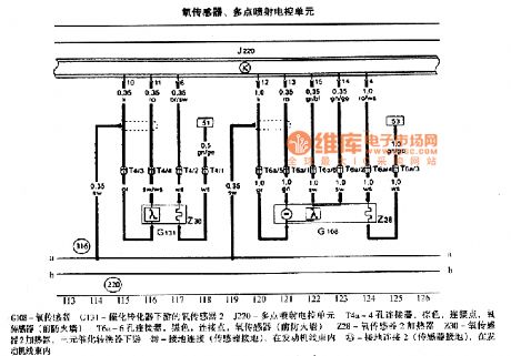
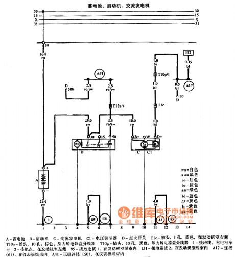
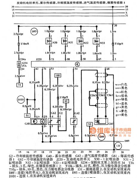
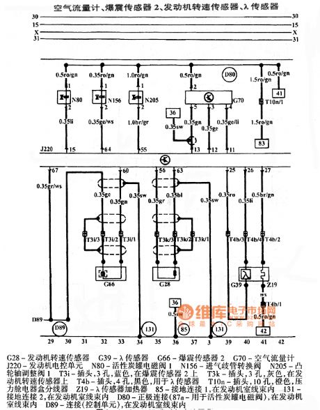
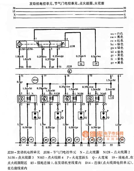
The pictures show the Audi A4 3.0L engine Circuits.
The first picture shows the battery, starting machine, AC generator, voltage adjustor, ignition starting switch.The second picture shows the fuel pump relay, multi-point injection control, engine electronic control system power supply relay.The third picture shows the multi-point injection ECU and injector.The fourth picture shows the air flow meter, multi-point injection ECU, activated carbon canister.The fifth picture shows the cooling fluid temperature sensor, multi-point injection ECU, camshaft correct timing adjustment valve, continuous cooling loop pump.The sixth picture shows the hall sensor, multi-point injection ECU.The seventh picture shows the oxygen sensor, multi-point injection ECU.The eighth picture shows the oxygen sensor, multi-point injection ECU. (View)
View full Circuit Diagram | Comments | Reading(984)
Audi A6 1.8T Engine Circuit
Published:2011/8/2 6:34:00 Author:Robert | Keyword: Audi, A6, 1.8T, Engine


The pictures show the Audi A6 1.8L engine circuits.
The first picture shows the battery, starting machine, AC generator.The second picture shows the engine ECU, hall sensor, cooling fluid temperature sensor, intake air temperature sensor, knock sensor 1.The third picture shows the air flow meter, knock sensor 2, engine speed sensor, λ sensor.The fourth picture shows the engine ECU, throttle ECU, ignition coil, spark plug.The fifth picture shows the engine ECU, ignition switch, oil surface level/temperature sensor, fuse.The sixth picture shows the engine ECU, fuel pump relay, fuel pump, fuel meter sensor.The seventh picture shows the reversing light, engine cooling system. (View)
View full Circuit Diagram | Comments | Reading(1185)
Meiri 4-Cylinder EFI A8 Engine Circuit
Published:2011/8/2 8:44:00 Author:Robert | Keyword: Meiri, 4-Cylinder, EFI, A8, Engine
The picture shows the Meiri 4-cylinder EFI A8 engine circuit.
In the picture the part 1 is generator. The part 2 is battery. The part 3 is starting machine. The part 4 is ignition switch. The part 5 is cassette players. The part 6 is speaker. The part 7 is relay. The part 8 is electronic clock. The part 9 is oil pump. The part 10 is computer. The part 11 is VSV value. The part 12 is oil injector. The part 13 is idle stabilization valve. The part 14 is speed sensor. The part 15 is knock sensor. The part 16 is oxygen sensor. The part 17 is air temperature sensor. The part 18 is cooling fluid temperature sensor. The part 19 is vacuum sensor. The part 20 is throttle position sensor. The part 21 is ignition device. The part 22 is fault diagnosis interface. And so on. (View)
View full Circuit Diagram | Comments | Reading(662)
Audi A6 Parking Hating Circuit
Published:2011/7/28 17:54:00 Author:Robert | Keyword: Audi, Parking, Hating
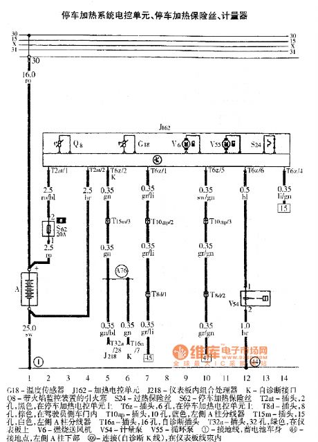

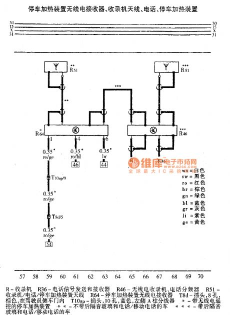
The pictures show the Audi A6 parking heating device circuits.
The first picture shows the parking heating system ECU, parking heating fuse and the meter device.
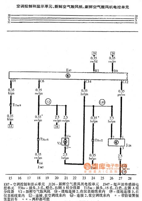
The second picture shows the air conditioner control and display unit, fresh air blower ECU.
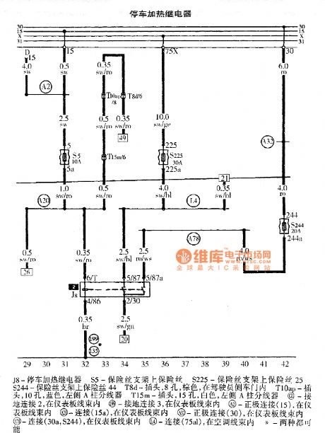
The third picture shows the parking heating relay.
The fourth picture shows the timer, heating indication lamp.
The fifth picture shows the parking heating device wireless receiver, tape recorders antenna, telephone, parking heating device. (View)
View full Circuit Diagram | Comments | Reading(859)
Audi A6 Central Door Lock, Anti-Theft Alarm System And Internal Monitoring Control System Circuit
Published:2011/7/28 18:16:00 Author:Robert | Keyword: Audi, Central Door, Lock, Anti-Theft, Alarm, Internal, Monitoring, Control


The pictures show the Audi A6 central door lock, anti-theft alarm system and internal monitoring control system circuits.
The first picture shows the ECU, engine hood anti-theft alarm contacting switch, central door lock and anti-theft device antenna, anti-theft alarm device.
The second picture shows the central door lock ECU, driver side-door lock switch.
The third picture shows the central door lock ECU, driver side-door contacting switch.
The fourth picture shows the central door lock ECU, front passenger side-door contacting lock, front passenger side-door internal lock switch.
The fifth picture shows the central door lock ECU, left door alarm lamp, right door alarm lamp.
The sixth picture shows the central door lock ECU, left-rear door contacting switch, right-rear door contacting switch. (View)
View full Circuit Diagram | Comments | Reading(2137)
BMW SRS basic circuit diagram
Published:2011/8/1 22:27:00 Author:Ecco | Keyword: BMW SRS , basic circuit

View full Circuit Diagram | Comments | Reading(737)
BMW remote control schematic circuit diagram
Published:2011/8/1 22:29:00 Author:Ecco | Keyword: BMW , remote control schematic

View full Circuit Diagram | Comments | Reading(677)
IMMOBILIZER
Published:2009/7/2 4:46:00 Author:May
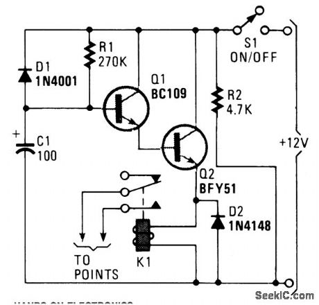
A flip of 51 puts the circuit into action. Power for the circuit is picked up from the ignition switch, and the circuit receives no power until the ignition switch is closed. When power is turned on, capacitor C1 is not charged and the emitter-follower Darlington pair (formed by Q1 and Q2) are cutoff, thus no power is applied to the relay (K1), which serves as Q1's emitter load. The relay's normally-open contacts are connected across the vehicle's points. (At this time, the relay contacts are open and have no effect on the ignition system). C1 charges by way of R1, causing the voltage at the base of Q1 to rise steadily. Thit creates a similar rise in the voltage at the emitter of Q2. A Darlington pair is used to provide a high input-impedance, buffer stage so that the voltage across C2 is free to rise almost to the full supply potential. Loading effects do not limit the charge potential to just a few volts. Eventually, the voltage applied to the relay becomes sufficient to activate it. The contacts close and short out the points. The ignition system now doesn't act properly and the vehicle is disabled. If the ignition is switched off, power is removed from the circuit and diode D1, which was previously reverse-biased, is now forward biased by the charge on C1. D1 allows C1 to rapidly discharge through R2 (and any other dc paths across the supply lines). The circuit is ready to operate when the ignition is again turned on. The engine will operate, but not for very long. The values of R1 and C1 provides a delay of about 25 to 30 seconds. Increase R1's value to provide a longer delay; (View)
View full Circuit Diagram | Comments | Reading(1411)
INTERMITTENT_WINDSHIELD_WIPER_WITH_DYNAMIC_BRAKING
Published:2009/7/2 4:45:00 Author:May

The circuit provides a delayed windshield wiping, and dynamic braking of wiper blades when they reach the rest position. This prevents the blades from overshooting, which might cause them to stop at a point where they interfere with the drivers' vision.With the original wiper switch off, switch S1A turns on the delay circuit and S1B disconnects the original automotive wiring. When S1 is tumed off, the original wiring controls the system and the delay circuit is bypassed.Turning S1 on applies the + 12-V battery to U1 which is a voltage doubler that produces + 18 V. This higher voltage supply is necessary to ensure reliable turn on of Q1 by multivibrator U2. This arrangement provides about +18 V to the gate of Q1, whose source is +12 V minus the VDS drop of Q1.Q1 remains on for a time determined by the WIPES potentiometer. The interval between wipes is controlled by the PAUSE control. When C1 drops below +4 V, U2 ftres, tuming Q1 on and restarting the cycle. (View)
View full Circuit Diagram | Comments | Reading(1066)
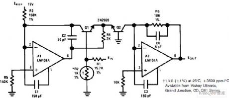
AUTOREFERENCE
Published:2009/6/30 3:15:00 Author:May
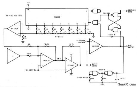
National CD4024C coni verter is used with logic and summer elements to elim inate virtually all offset errors induced by time and temperature changes in process coni trol system fed by transducer. Best suited for applications having short repeated duty cycles, each containing reference point. Examples indude weighinga scalein which transducer is load cell, pressure control systems, fuel pumps, and sphygmomanometers. Circuit eliminates warm-up emors.— Pressure Transducer Hand-book, National Semiconductor, Santa Clara, CA, 1977, p 7-4-7-8. (View)
View full Circuit Diagram | Comments | Reading(553)
Suzuki elevator brake circuit (B)
Published:2011/7/23 10:41:00 Author:John | Keyword: elevator brake

View full Circuit Diagram | Comments | Reading(652)
8038 function generator circuit
Published:2011/7/19 22:19:00 Author:John | Keyword: function generator

The figure shows the 8038 function generator circuit. Function generator formed by integrated circuit chip 8038 can obtain square wave, triangle wave and sine wave at the same time. Triangle wave can be generated directly by the capacitor discharge current. And square wave can be obtained by control signal. The sine wave is obtained by the broken line approximation circuit from the triangle wave. The sine curve obtained in this way is not a smooth line, whose distortion was about 1 percent. The needs for general purpose can be met. PR1 in the potentiometer circuit is used to adjust the frequency to be ranged from 20 Hz to 20 kHz. PR2 is used to adjust the waveform’s distortion and PR3 is used to adjust the waveform's duty cycle.
(View)
View full Circuit Diagram | Comments | Reading(7546)
500 candela flash circuit
Published:2011/7/28 21:33:00 Author:John | Keyword: flash, 500 candela flash
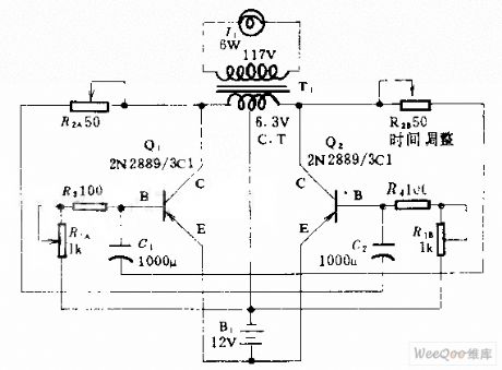
This circuit can be used at night as the flash for dock instruction or rescue vehicle. The flash can be D26-type or 6S6 type of 117V and 6W. Q1 and Q2 form an oscillator alter battery’s direct current into alternating current. The AC can be used as boost power supply for T1. Double potentiometer R2 adjusts the duration of each flash and R1 adjusts the flash frequency.
(View)
View full Circuit Diagram | Comments | Reading(513)
Anti-Chi generator circuit
Published:2011/7/28 21:27:00 Author:John | Keyword: generator
Anti-Chi generator circuit is shown.
(View)
View full Circuit Diagram | Comments | Reading(1350)
notch filter with easy adjustment circuit
Published:2011/7/28 21:26:00 Author:John | Keyword: notch filter

Notch filter with easy adjustment circuit is shown.
(View)
View full Circuit Diagram | Comments | Reading(590)
| Pages:33/164 At 202122232425262728293031323334353637383940Under 20 |
Circuit Categories
power supply circuit
Amplifier Circuit
Basic Circuit
LED and Light Circuit
Sensor Circuit
Signal Processing
Electrical Equipment Circuit
Control Circuit
Remote Control Circuit
A/D-D/A Converter Circuit
Audio Circuit
Measuring and Test Circuit
Communication Circuit
Computer-Related Circuit
555 Circuit
Automotive Circuit
Repairing Circuit