
Automotive Circuit
Index 36
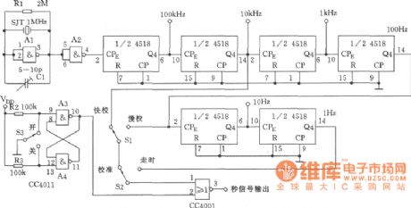
Second-signal circuit (CC4518, CC4001) circuit
Published:2011/7/23 9:28:00 Author:John | Keyword: Second-signal circuit
View full Circuit Diagram | Comments | Reading(428)
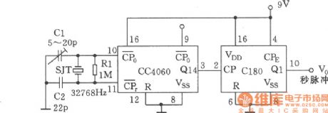
CC4060 second-signal generator circuit
Published:2011/7/23 9:29:00 Author:John | Keyword: second-signal generator
View full Circuit Diagram | Comments | Reading(441)
Multi-phase shift signal generator circuit
Published:2011/7/23 9:29:00 Author:John | Keyword: shift signal generator, Multi-phase shift signal generator
View full Circuit Diagram | Comments | Reading(560)
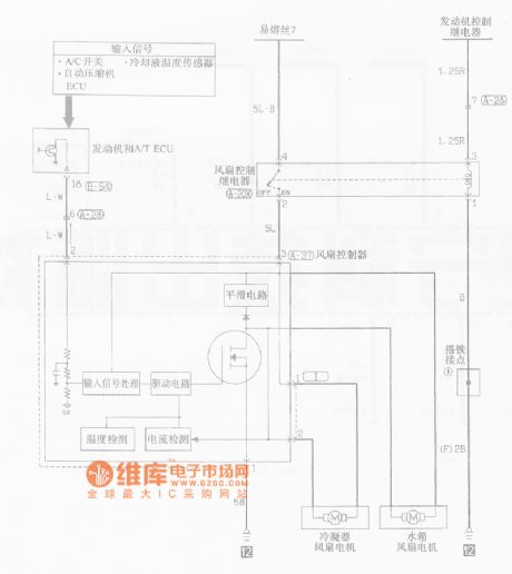
Southeast Soveran cooling system circuit
Published:2011/7/23 9:29:00 Author:John | Keyword: cooling system
View full Circuit Diagram | Comments | Reading(388)
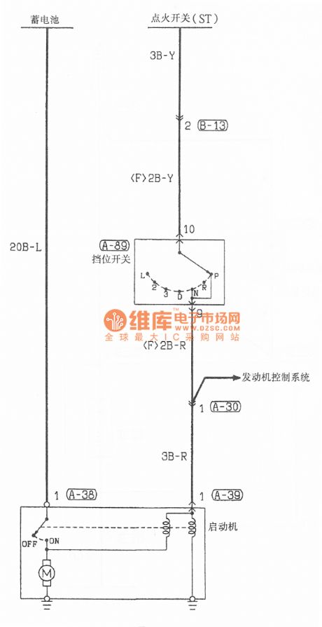
Southeast Soveran starting system circuit
Published:2011/7/23 9:30:00 Author:John | Keyword: starting system
View full Circuit Diagram | Comments | Reading(411)
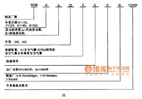
Benz C220 WDB H A22 EXRH 123456 identification code circuit diagram
Published:2011/7/20 20:17:00 Author:Ecco | Keyword: Benz, WDB, H , A22 , EXRH, 123456 , identification code
View full Circuit Diagram | Comments | Reading(402)
MOTION_ACTIVATED_MOTORCYCLE_OR_CAR_ALARM
Published:2009/6/22 23:47:00 Author:May
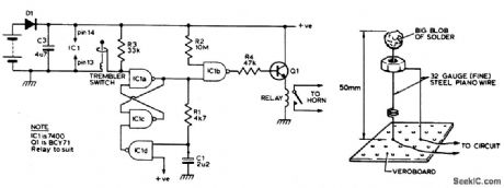
Trembler (motion activated) switch sounds the alarm for 5 seconds. Then it goes off. Circuit is timed out for 10 seconds to allow the trembler switch to settle. (View)
View full Circuit Diagram | Comments | Reading(1234)
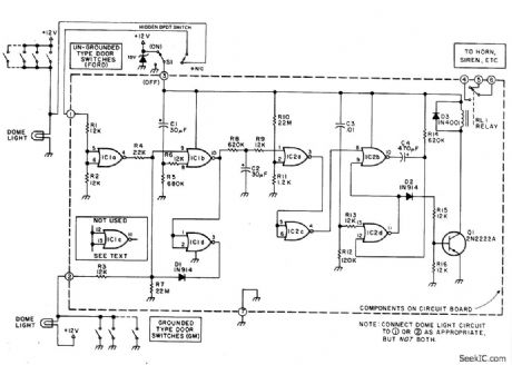
AUTO_BURGLAR_ALARM
Published:2009/6/22 23:44:00 Author:May

Dome light current through L1 closes reed switch and sounds alarm. Shaker switch also activates alarm. (View)
View full Circuit Diagram | Comments | Reading(1000)
VEHICLE_SECURITY_SYSTEM
Published:2009/6/22 23:39:00 Author:May
This alarm gives a 15-20 second exit and entrance delay. After being triggered, the alarm sounds for five minutes and then shuts off. Once triggered, the sequence is automatic and is not affected by subsequent opening or closing of doors. (View)
View full Circuit Diagram | Comments | Reading(0)
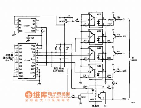
The light isolation data collecting system circuit
Published:2011/7/21 2:35:00 Author:Seven | Keyword: data collecting system
View full Circuit Diagram | Comments | Reading(413)
The loudspeaker power amplitude limiter circuit
Published:2011/7/24 7:35:00 Author:Seven | Keyword: power amplitude limiter
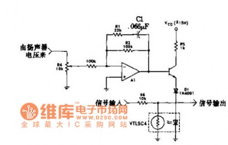
In the figure is the circuit which utilizes the amplitude limiter to reduce the low frequency power. Under 200HZ, the circuit limits the threshold voltage. When it is low frequency, the amplifier A1 gain is 1. The amplifier is starting when it is 25HZ, the gain is 6Db/octave, and it is cut off, R4 is used to adjust the impedance. VBE of Q1, voltage drop of D1, voltage of LED, they together set the threshold voltage which is 2.8V or so(peak) or 2.0V(RMS). A01 is used to weaken the signal voltage.
(View)
View full Circuit Diagram | Comments | Reading(803)
MOTORCYCLE_TUNE_UP_AID
Published:2009/6/22 22:28:00 Author:May
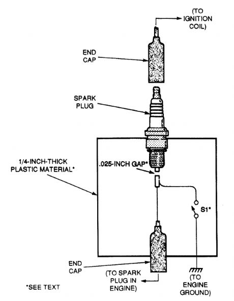
Performing a tune-up on a newer bike is made a lot easier with this helpful circuit. Because of the high voltages present, make sure that S1 has an insulated handle and that the fixture is grounded. With the ignition turned off, remove one of the spark plug wires and connect it to the spark plug on the fixture. Slip the fixture's end cap over the spark plug on the cycle and you're ready to go. Open S1 and start the engine. Then, close S1; the cylinder with the fixture should not fire and a spark should be seen at the fixed gap. Be sure that the fixture is cqnnected to the engine ground before closing S1 . (View)
View full Circuit Diagram | Comments | Reading(519)
AUTOMOTIVE_HI_ZTEST_LIGHT
Published:2009/6/19 2:41:00 Author:May
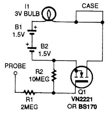
This test Iight has a high-input impedance and draws only 1 mA at 12V. Q1 switches dc to a battery and lamp circuit. (View)
View full Circuit Diagram | Comments | Reading(437)
SMART_TURN_SIGNAL_FOR_AUTOS_AND_MOTORCYCLES
Published:2009/6/19 2:24:00 Author:May
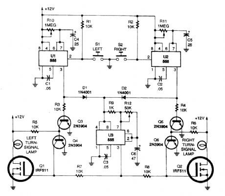
Momentarily pressing S1 starts the left on-time timer and produces a positive output at pin 3 of U1. Power for the on/off signal timer, U3, is supplied through D1.Also, a positive bias is supplied from U1's output to the base of Q3, turning it on and turning Q4 off. Unclamped Q1 turns the left turn-signal lamp on and off at that same low-frequency rate. Because U2 is not activated, its output at pin 3 is low, keeping Q5 off. With Q5 turned off, Q6 is on, clamping the gate of Q2 to ground and keeping it from responding and supplying an output for the right turn-signal lamp. The left turn signal continues to operate until the UI timer circuit times out; the right turn signal operates in a similar manner, with U2 setting its operating time.Potentiometer R10 sets the running time for the left turn signal and R11 sets that for the right turn signal. (View)
View full Circuit Diagram | Comments | Reading(582)
TACHOMETER_SIGNAL_CONDITIONING_CIRCUIT
Published:2009/6/19 2:21:00 Author:May

This circuit, for use with auto tachometers, cleans up the ragged distribution waveform before it is sent to pulse counter circuits. (View)
View full Circuit Diagram | Comments | Reading(803)
MOTORCYCLE_TURN_SIGNAL_SYSTEM
Published:2009/6/19 2:20:00 Author:May

Tired of making hand signals? Build this simple turn-signal system and keep your hands on the handlebars. (View)
View full Circuit Diagram | Comments | Reading(140)
AUTOMOTIVE_ELECTRICAL_MONITOR
Published:2009/6/19 2:10:00 Author:May
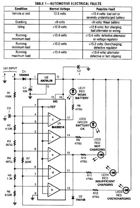
The automotive electrical diagnostic system is built around a Maxim MAX8214ACPE five-stage voltage comparator, which contains a built-in 1.25-volt precision reference, and on-board logic that allows the outputs of two of the comparators to be inverted. (View)
View full Circuit Diagram | Comments | Reading(744)
ELECTRONIC_AUTO_STETHOSCOPE
Published:2009/6/19 2:06:00 Author:May

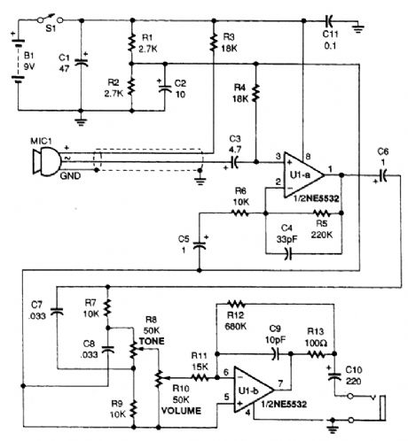
The heart of the Stethoscope is the NE5532 audio op amp, UI. That component directly drives low impedances and allows the use of headphones without adding another amplifier. (View)
View full Circuit Diagram | Comments | Reading(748)
Beijing Hyundai Sonata motor-driven door and window switch circuit diagram
Published:2011/5/6 3:41:00 Author:muriel | Keyword: Beijing Hyundai Sonata, motor-driven, door and window, switch

Beijing Hyundai Sonata motor-driven door and window switch circuit diagram is as shown
(View)
View full Circuit Diagram | Comments | Reading(852)
AUTO_SECURITY_SYSTEM_TRANSMITTER
Published:2009/6/17 23:20:00 Author:May

This transmitter operates at 49 MHz and uses an M145026 programmable digital encoder to generate a unique digital code, depending on the positions of S2 and S3, to control ignition and lights or horn. Q1 is the oscillator, Q2 the power amplifier. The antenna is a 36-inch whip or wire antenna. (View)
View full Circuit Diagram | Comments | Reading(2032)
| Pages:36/164 At 202122232425262728293031323334353637383940Under 20 |
Circuit Categories
power supply circuit
Amplifier Circuit
Basic Circuit
LED and Light Circuit
Sensor Circuit
Signal Processing
Electrical Equipment Circuit
Control Circuit
Remote Control Circuit
A/D-D/A Converter Circuit
Audio Circuit
Measuring and Test Circuit
Communication Circuit
Computer-Related Circuit
555 Circuit
Automotive Circuit
Repairing Circuit