
Automotive Circuit
Index 35
BUZZER_FOR_IDIOT_LIGHT
Published:2009/6/28 22:36:00 Author:May

Provides audible supplement to engine-monitoring indicator lamps that are often difficuh to see in daylight. Uses 2N5434 JFET to provide delay of about 7 s each time ignition switch isturned on,to allow for peaceful starting of car and normal buildup of oil pressure when lamp is monitoring oilpressure and engine-temperature sensors. Entire circuit can be mounted inside plastic housing of unused or disconnected dashboard warning buzzer in late-model car.-P. Glower, Audio Assist Gives Idiot Lights the Buzz. EDN Magazine, June 20, 1976, p 126. (View)
View full Circuit Diagram | Comments | Reading(634)
COLD_WEATHER_IGNITION
Published:2009/6/28 22:25:00 Author:May

Multispark electronic ignition improves cold-weather starting ability of engines in arctic environment by providing more than one spark per combustion cycle. Circuit uses UJT triangle-wave generator Q1, emitter-follower isolator Q2, wave-shaping Schmitt trigger Q3-Q4, three stages of squarewave amplification Q5-Q7, and output switching circuit Q8 all operating from 12-V negative-ground supply. 6.2-V zener provides regulated voltage for UJT and Schmitt trigger. Initial 20,-000- to 40,000-V ignition spark produced by opening of breaker points is followed by continuous series of sparks at rate of about 200 per second as long as points stay open.-D. E. Stinchcomb, Multi-Spark Electronic Ignition for Engine Stating in Arctic Environment, Proceedings of the IEEE 1975 Region Six Conference, May 1975, p 224-225. (View)
View full Circuit Diagram | Comments | Reading(1094)
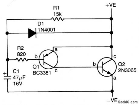
VOLTAGE_REGULATOR
Published:2009/6/28 22:17:00 Author:May

Time and power Darlington form simple automobile voltage regulator. When batteru voltage drops below 14.4 V , timer is turned on and Darlington pair conducts. Separate adjustments are provided for preset turn-on and turnoff voltages.- signetics Analog Data Manual. Signetics, Sunnyvale, CA, 1977, p 731. (View)
View full Circuit Diagram | Comments | Reading(0)
HEADLIGHT_REMINDER_1
Published:2009/6/28 22:12:00 Author:May

Photocell energizes circuit at twilight to remind motorist that lights should be turned on. Indicator can be LED connected as shown or relay turning on buzzer for more positive signal. Circuit can be made au-tomatic by connecting relay contacts in parallel with light switch, provided delay circuit is added to prevent oncoming headlights from killing circuit. Mount photocell in location where it is unaffected by other lights inside or outside car.-J. Sandier, 9 Projects under $9, Modern Electronics, Sept. 1978, p 35-39. (View)
View full Circuit Diagram | Comments | Reading(707)
TRANSISTORIZED_BREAKER_POINTS
Published:2009/6/28 22:09:00 Author:May

Uses Texas Instruments BUY23/23A high-voltage transistors that can easily withstand voltages up to about 300V existiong across breaker points of distributor in modern car. Circuit serves as electronic switch that isolates points fro;yt heavy interrupt current and high-voltage back-swing of Ignition coil, thereby almost completely eliminating wear on points. Values are: Tr2 2N3789; Tr3 (for positive ground version) 2N3055; D1-D4 1N4001; D5 18-V 400-mW zener; R1 56 ohm; R2 1.2 ohms; R3 10 ohms; C 600 VDC same size as points capacitor. Article covers installation procedure.-G.F. Nudd, Transistor-Aided Ignition, Wireless World, April 1975, p 191. (View)
View full Circuit Diagram | Comments | Reading(1514)
AUTOMATIC_CONTRAST_METER
Published:2009/6/28 20:48:00 Author:May

The circuit arrangement consists of a photo-amplifier which feeds a voltage derived from varying light levels in an enlarger to a pair of peak detectors. One follows the peak positive voltage and the other the peak negative voltage. The capacitors used for storing the voltage peaks in the followers also form part of sample and hold circuits which are then switched to hold after the measurement. Their outputs represent the maximum and minimum values of light intensity. A differential amplifier then computes the ratio of these values, and the result is displayed on an LED bargraph meter. (View)
View full Circuit Diagram | Comments | Reading(776)
SOLID_STATE_AUTO_REGULATOR
Published:2009/6/28 21:06:00 Author:Jessie

Replaces and outperforms electromechanical charging-voltage regulator in autos using altemator systems. Prolongs battery life by preventing un dercharging or overcharging of 12-V lead-acid battery. Uses LM723 connected as sia;itching regulatorfor controlling altematorfield cument. R2 is adjusted to maintain 13.8.V fully charged voltage for standard auto battery. Article gives construction details and tells how to use external relay to maintain altemator charge-indica-torfunction in cars having idiot light ratherthan charge-discharge ammeter. Q1 is 2N2063A (SK3009) 10-A PNP transistor.-W. J. Prudhomme, Build Your Own Car Regulator, 73 Magazine, March 1977, p 160-162. (View)
View full Circuit Diagram | Comments | Reading(4209)
UNIVERSAL_MOTOR_SPEED_CONTROL_WITH_LOAD_DEPENDENT_FEEDBACK(FOR_MIXER,SEWING_MACHINE,ETC)
Published:2009/6/25 23:40:00 Author:May

Simple half-wave motor speed control is effective for use with small universal (ac/dc) motors. Maximum current capability 2.0 amps RMS. Because speed-dependent feedback is provided, the control gives excellent torque characteristics to the motor, even at low rotational speeds. Normal operation at maximum speed can be achieved by closing switch S1, thus bypassing the SCR. (View)
View full Circuit Diagram | Comments | Reading(0)
AUTO_BATTERY_CURRENT_ANALYZER
Published:2009/6/24 4:23:00 Author:May

This op-amp analyzer can measure the current drawn by any device in a car. The analyzer works by measuring the very small voltage that develops across the battery cables when current flows. To calibrate the unit, mea-sure the current flow somewhere in the car with an accurate ammeter, then adjust the analyzer for that current reading. (View)
View full Circuit Diagram | Comments | Reading(680)
TACHOMETER_1
Published:2009/6/24 4:21:00 Author:Jessie
View full Circuit Diagram | Comments | Reading(488)
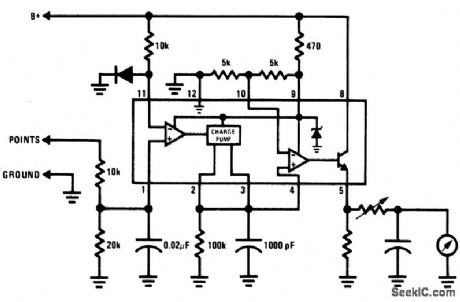
BREAKER_POINT_DWELL_METER
Published:2009/6/24 4:19:00 Author:Jessie
View full Circuit Diagram | Comments | Reading(0)
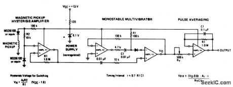
TACHOMETER
Published:2009/6/24 4:10:00 Author:Jessie
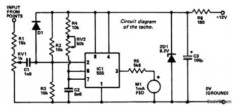
An electrical signal taken from the low tension side of the distributor is converted into a voltage proportional to engine rpm and this voltage is displayed on a meter calibrated ac-cordingly. The 555 timer IC is used as a monostable which, in effect, converts the sig-nal pulse from the breaker points to a single positive pulse the width of which is determined by the value of R4 + RV2 and C2. Resistors R2 and R3 set a voltage of about 4 volts at pin 2 of IC1. The IC is triggered if this voltage is re-duced to less than approximately 2.7 volts (1/3 of supply voltage), and this occurs due to the voltage swing when the breaker points open.An adjustment potentiometer RV1 enables the input level to be set to avoid false triggering. Zener diode ZD1 and the 180 ohm resistor stabilize the unit against voltage variations. (View)
View full Circuit Diagram | Comments | Reading(4)
BARGRAPH_CAR_VOLTMETER
Published:2009/6/24 4:08:00 Author:Jessie

The LM3914 acts as a LED-driving vol-tometer that has its basic maximum and minimum readings determined by the values of R2 and RV2. When correctly adjusted, the unit actually covers the 2.5 volt to 3.6 volt range, but it is made to read a supply voltage span of 10-10.5 volts to 15 volts by interposing poten-tial divider R1-RV1 between the supply line and the pin-5 input terminal of the IC. The IC is configured to give a 'dot' display, in which only one of the ten LEDs is illuminated at any given time. If the supply voltage is below 10.5 volts none of the LEDs illuminate. Ifthe supply equals or exceeds 15 volts, LED 10 illuminates. (View)
View full Circuit Diagram | Comments | Reading(0)
COURTESY_LIGHT_EXTENDER
Published:2009/6/24 4:07:00 Author:Jessie
Most car door switches are simply single-pole switches, with one side grounded. When the door is opened the switch grounds the other line thus completing the light circuit. In a car where the negative terminal of the battery is connected to the chassis, the,.g,J tive wire of the unit (emitter of Q2) is con-nected to chassis the positive wire (case of 2N3055) is connected to the wire going to the switch. 1n a car having a positive ground sys-tem this connection sequenge is reversed. When the switch closes (door open), C1 is discharged via D1 to zero volts, and when the switch opens, g| charges up via R1 and R2.Transistors Q1 and Q2 are connected as an emitter follower (Q2 just buffers Q1) therefore the voltage across Q2 increases slowly as Ci charges. Hence Q2 acts like a low resistance in parallel with the switch and keeps the lights on.The value of C1 is chosen such that a usetui light level is obtained for about four seconds; therefore the light decreases until in about 10 seconds it is out completely. With different transistor gains and with variation in current drain due to a particular type of car, the timing may vary but may be simply adjusted by selecting C1. (View)
View full Circuit Diagram | Comments | Reading(0)
UNIVERSAL_WIPER_DELAY
Published:2009/6/24 4:04:00 Author:Jessie

IC1 is connected in the astable mode, driving RLA. C3, Dl, and D2 prevent spikes from the relay coil and the wiper motor from triggering IC1. VR2 is adjusted to give the minimum delay time required. VR1 is the main delay control and provides a range of from about 1 second to 20 seconds. SW1 is an over-ride switch to hold RLA permanently on (for normal wiper operation). The relay should have a resistance of at least 150 ohms and have heavy duty contacts. The suppression circuit may be needed for the protection of IC1. (View)
View full Circuit Diagram | Comments | Reading(1938)
OPERATING_WAVEFORMS
Published:2009/6/24 4:03:00 Author:Jessie

View full Circuit Diagram | Comments | Reading(863)
SPEED_WARNING_DEVICE
Published:2009/6/24 4:03:00 Author:Jessie
View full Circuit Diagram | Comments | Reading(0)
c8051f Simulator EC3
Published:2011/7/12 2:02:00 Author:Sue | Keyword: Simulator
a) EC3 simulator is the latest series of MCU, and it uses the core technology of Silabs company.
b) It can realise functions as single step, hardware breakpoint, continuous single step, start and stop, modification and inspection of container and register, download of programs and encryption.
c) EC3 has the same functions as SILABS company's EC3.
It is the only domestic product that uses core technology of the origin company, so please recognize out signal C8015F Network . (View)
View full Circuit Diagram | Comments | Reading(423)
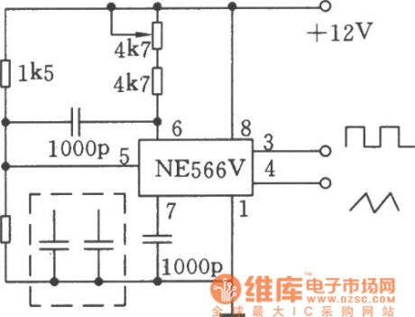
using NE566V for composing 20kHz waveform generator circuit
Published:2011/7/23 9:27:00 Author:John | Keyword: waveform generator
View full Circuit Diagram | Comments | Reading(526)
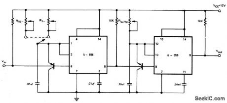
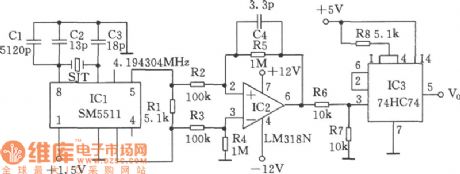
Precise second-pulse signal generator circuit
Published:2011/7/23 9:28:00 Author:John | Keyword: second-pulse signal generator
View full Circuit Diagram | Comments | Reading(484)
| Pages:35/164 At 202122232425262728293031323334353637383940Under 20 |
Circuit Categories
power supply circuit
Amplifier Circuit
Basic Circuit
LED and Light Circuit
Sensor Circuit
Signal Processing
Electrical Equipment Circuit
Control Circuit
Remote Control Circuit
A/D-D/A Converter Circuit
Audio Circuit
Measuring and Test Circuit
Communication Circuit
Computer-Related Circuit
555 Circuit
Automotive Circuit
Repairing Circuit