
Automotive Circuit
Index 37
DIMMER_FOR_LOW_VOLTAGE_LOADS
Published:2009/6/17 2:02:00 Author:May

This circuit controls a low voltage dc supply by pulse width modulation. The switching rate is 200 Hz. Input supply voltage should be +5 to +30 V. Up to 5 A can be controlled. (View)
View full Circuit Diagram | Comments | Reading(636)
CAR_BATTERY_AND_ALTERNATOR_MONITOR
Published:2009/6/17 1:51:00 Author:May


The monitor is a simple voltage comparator in which a car battery serves as the battery for op-eration. The input voltage to the comparator is set by adjustment potentiometer P1, which must be adjusted so that the green LED L2 is on when the altemator is operating properly and red LED1 is on when the altemator is inoperative.The circuit operates as follows: When the alternator operates properly, the battery voltage is higher and P1 is set so that transistor Q1 causes Q2 to be off. That results in Q3 and Q4 being fully on, thus applying current to green LED L2. If the battery voltage is lowered (alternator inoperative), transistor Q1 is turned off. That allows transistor Q2 to turn fully on, applying current to red LED L1, indicating trouble. Once Q2 is on, it causes Q3 and Q4 to go out of conduction. (View)
View full Circuit Diagram | Comments | Reading(1394)
LIGHTS_ON_REMINDER
Published:2009/6/16 3:00:00 Author:May

A relay and two diodes are all that is needed-the relay performs the job of a buzzer so no annun-ciator is required. When the lights are left on, but the ignition is off, the normally closed relay contacts are in series with the relay coil. That means the relay interrupts its own power each time it becomes active, so it chatters and acts fie a buzzer.This is a real minimalistic headlight reminder. It doesn't even require an annunciator because the relay acts as buzzer. (View)
View full Circuit Diagram | Comments | Reading(3)
AUTO_GENERATOR_REGULATOR
Published:2009/6/16 2:53:00 Author:May


This regulator is for the purpose of controlling a dc generator. The field configuration is that one side of the field is grounded. D4 prevents the battery from discharging through the generator and takes the place of the mechanical cut-out relay. R10 adjusts the system voltage setting. (View)
View full Circuit Diagram | Comments | Reading(1)
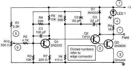
ALTERNATOR_REGULATOR
Published:2009/6/16 2:52:00 Author:May


This alternator regulator uses a 3-transistor dc amplifier, and is designed for a pulled up field system, where one side of the alternate field returns to the +12-Vsupply, and the other end is pulled toward ground. The circuit monitors the state of the battery through a resistive divider and causes the voltage to change at the field terminal. (View)
View full Circuit Diagram | Comments | Reading(7011)
AUTOMATIC_TURN_OFF_CONTROL_FOR_AUTOMOBILES
Published:2009/6/16 2:49:00 Author:May

When the ignition switch is on, relay K1 is energized continuously, and the headlights can be Lumed on. Turning off the ignition turns on timer IC1,which keeps IC1 energized for a time deter-mined by R1 and C1. With the values shown approximately a 1 minute delay wilLresult. The values of R1 or C1 can ve changed to vary this delay time. (View)
View full Circuit Diagram | Comments | Reading(629)
AUTOMOTIVE_AUDIBLE_TURN_INDICATOR
Published:2009/6/16 2:41:00 Author:May
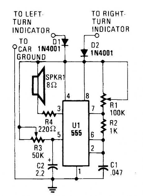
This little circuit should be useful to the hearing impaired. It produces a tone each time a dashboard turn indicator lights. The tone drops in frequency for as long as the indicator is lit. (View)
View full Circuit Diagram | Comments | Reading(466)
BOOSTER_AMPLIFIER_FOR_CAR_STEREO_USE
Published:2009/6/16 2:31:00 Author:May


Only one channel of this circuit is shown. The other is practically a carbon copy.The input to the circuit, taken from your car radio's speaker output, is divided along two paths; in one path, a high-power divider network (consisting of R8 through R10) provides 4.5-Ω resistance to make the circuit's input impedance compatible with the output irrtpedance of the car radio. In the other path, the signal is fed to the input of U1 through resistor LR7, trimmer potentiometer R21, and capacitor C2. Together, R7 and R21 offer a minimum resistance of 27,000 Ω.Integrated circuit U1 (a TDA-2004 audio power amplifter) ampliftes the signal, which is then out-put at pins 8 and 10 and fed to the loudspeaker. Note: This amp is designed for use only with car radios whose speaker outputs are referenced to ground: do not use it with radios that have balanced outputs. (View)
View full Circuit Diagram | Comments | Reading(2010)
AUTOMOTIVE_POWER_ADAPTER_FOR_dc_OPERATED_DEVICES
Published:2009/6/16 2:25:00 Author:May
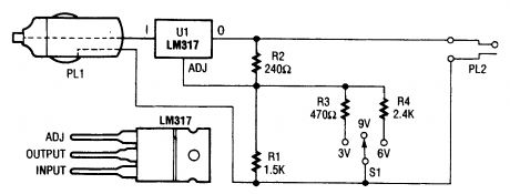
In the schematic diagram for the car-power adapter, note how the value of RB (which is R1 and S1 in the center position) is changed by putting R3 or R4 in parallel with R1. (View)
View full Circuit Diagram | Comments | Reading(473)
POWER_CONTROLLER_FOR_AUTOMOTIVE_ACCESSORIES
Published:2009/6/16 2:23:00 Author:May

Because the power controller is powered from the vehicle's accessory switch, the load can receive power only when the ignition key is on. Using half of a dual flip-flop (CD4013), a load of up to 10 A is controlled by a momentary pushbutton. This circuit was originally intended for automotive power control, but could have other applications as well. (View)
View full Circuit Diagram | Comments | Reading(1187)
FLASHING_BRAKE_LIGHT
Published:2009/6/16 2:19:00 Author:May
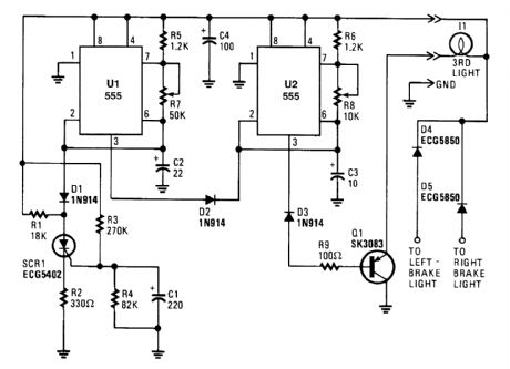
When power is first applied, three things happen: the light-driving transistor (Q1) is switched on because of a low output from U2, pin 3; timer U1 begins its timing cycle, with the output (pin 3) going high, inhibiting U2's trigger (pin 2) via D2; and charge current begins to move through R3 and R4 to C1.When U1's output goes low, the inhibiting bias on U2 pin 2 is removed, so U2 begins to oscillate, flashing the third light via Q1, at a rate determined by R8, R6, and C3. Oscillation continues until the gate-threshold voltage of SCR1 is reached, causing it to fire and pull U1's trigger (pin 2) low. With its trigger low, U1's output is forced high, disabling U2's triggering. With triggering inhibited, U2's out-put switches to a low state, which makes Q1 conduct, turning on I1 until the brakes are released. Removing power from the circuits resets SCR1, but the RC network consisting of R4 and C1 will not discharge immediately and will trigger SCR1 earlier. So, frequent brake use means fewer flashes.Bear in mind that the collector/emitter voltage drop across Q1, along with the loss across the series-fed diodes, reduces the maximum available light output. If the electrical system is functioning properly (at 13 to 14 V for most vehicles), those losses will be negligible. (View)
View full Circuit Diagram | Comments | Reading(611)
THERMOSTAT_SEITCH_FOR_AUTOMOTIVE_ELECTRIC_FANS
Published:2009/6/16 2:13:00 Author:May

The circuit is based on a commercial temperature sensor(TS6178) and an MC3334P ignition chip. When the radiator temperature increases, the sensor pulls the base of Q2 low via Q1, which is wired as a diode. Q2's collector thus goes high and triggers IC1, which seitches its pin 7 output high and turns on the fan motor via Q3. (View)
View full Circuit Diagram | Comments | Reading(489)
MANUAL_HEADLIGHT_SPOTLIGHT_CONTROL_FOR_AUTOS
Published:2009/6/16 2:07:00 Author:May
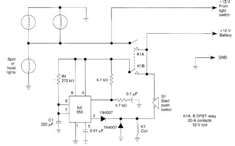
Pressing the START pushbutton turns on either the headlights or spotlights for a predtermined time. After 1 minute (R1 and C1 determine this), the lights will shut off as the NE555 completes its cycle. (View)
View full Circuit Diagram | Comments | Reading(580)
VEHICULAR_TACHOMETER_CIRCUIT
Published:2009/6/16 1:49:00 Author:May
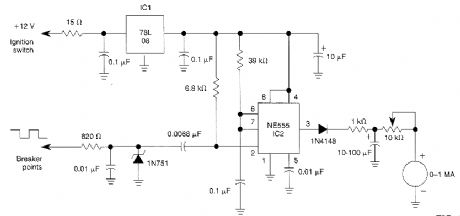
In this automotive application, the 555 is a pulse counter. IC1 regulator provides proper operating voltage for IC2. This circuit is for vehicles with conventional breaker points. (View)
View full Circuit Diagram | Comments | Reading(648)
The car electric igniter (5)
Published:2011/7/21 20:42:00 Author:qqtang | Keyword: electric igniter
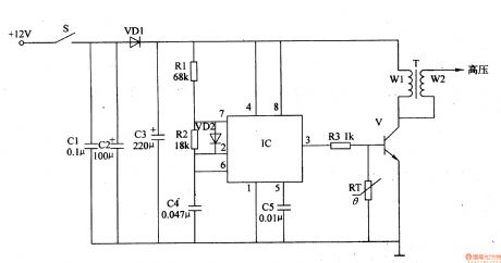
Here is to introduce the car electric igniter, which is made on the base of the 555 time-based integrated circuit, and it characterizes high igniting voltage(which can reach 15-20KV), low starting temperature of the engine, energy-saving and so on. The working principle The car electric igniter consists of the filter circuit, pulse oscillator circuit and switch booster circuit, see as figure 7-136.
The filter circuit consists of the filter capacitor C1-C3 and isolating diode VD1. (View)
View full Circuit Diagram | Comments | Reading(1509)
The car back-up alarm (2)
Published:2011/7/22 22:13:00 Author:qqtang | Keyword: back-up alarm

The working principle of the circuit The car back-up alarm consists of the sound alarm circuit and op-amp output circuit, see as figure 7-122.
The sound alarm circuit consists of the switch S, resistors of R1 and R2, capacitor C1, voltage stabilizing diode VS and 3-terminal sound alarm integrated circuit IC. The op-amp output circuit consists of the power amplifier integrated circuit IC2, capacitors C2-C5, resistor R3 and loudspeaker BL. (View)
View full Circuit Diagram | Comments | Reading(1161)
The car back-up alarm (3)
Published:2011/7/22 22:22:00 Author:qqtang | Keyword: back-up alarm

The car back-up alarm that will be introduced adopts the voice integrated circuit, which can make the alarm sound of ding-dong, back up to remind the pedestrian of safety.The working principle of the circuitThe car back-up alarm consists of the sound generator and the op-amp output circuit, see as figure 7-123.
The sound generator circuit consists of the resistors R1-R3, capacitors of C2 and C4, regulated diode VS and voice integrated circuit IC (View)
View full Circuit Diagram | Comments | Reading(1202)
The automobile steering alarm (1)
Published:2011/7/22 21:18:00 Author:qqtang | Keyword: steering alarm
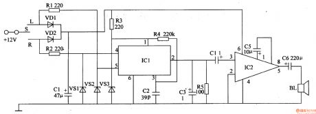
The working principle of the circuit The automobile steering alarm consists of the audio trigger circuit and audio amplifier output circuit, see as figure 7-124.
The audio trigger circuit consists of the resistors R1-R4, diodes of VD1 and VD2, capacitors of C1 and C2, regulated diodes of VS1-VS2 and audio integrated circuit IC1. The audio amplifier output circuit consists of the resistors C3-C6, resistor R5, audio power amplifier integrated circuit IC2 and loudspeaker BL. (View)
View full Circuit Diagram | Comments | Reading(449)
The automobile steering alarm (2)
Published:2011/7/22 21:25:00 Author:qqtang | Keyword: steering alarm

The working principle of the circuitThe automobile steering alarm consists of the square wave oscillator, flash control circuit and music generator circuit, see as figure 7-125.
The square wave oscillator consists of the NAND circuit IC1(D1 and D2), resistors R1-R3, regulated diode VS and capacitor C1.The flash control circuit consists of the resistor R4, transistor V1, diode VD3 and relay K.The music player consists of the transistor V2, resistors R5-R7, capacitor C2, music integrated circuit IC2 and loudspeaker BL.
(View)
View full Circuit Diagram | Comments | Reading(414)
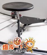
Supply Camera Rail Car
Published:2011/7/19 6:50:00 Author:Sue | Keyword: Camera Rail Car, Imported, Photographic Rail Car

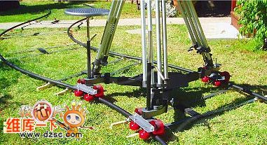


Features:
It can bear at most 200kg.
It can be equipped with any professional tripod, and can install a small camera arm.
It has a standard cameraman seat and a push bar which facilitates camera in seat and track sliding movement.
The track interface is seamlessly connected and is smooth and stable. The track width can be adjusted at random and is suitable fordifferent environments/filming sites.
The track uses aviation aluminum alloy which has 17 layers of surface coating and is not easy to wear out.
It doesn't need any installation tools and is portable and easy to use. It can solve the problems of low frequency which results from heavy stainless steel rail,overload and inconvenient transportation. (View)
View full Circuit Diagram | Comments | Reading(531)
| Pages:37/164 At 202122232425262728293031323334353637383940Under 20 |
Circuit Categories
power supply circuit
Amplifier Circuit
Basic Circuit
LED and Light Circuit
Sensor Circuit
Signal Processing
Electrical Equipment Circuit
Control Circuit
Remote Control Circuit
A/D-D/A Converter Circuit
Audio Circuit
Measuring and Test Circuit
Communication Circuit
Computer-Related Circuit
555 Circuit
Automotive Circuit
Repairing Circuit