
Automotive Circuit
Index 28
The circuit diagram of a logic-pen that can shows the open state (CD4001) 1st
Published:2011/8/8 21:43:00 Author:Felicity | Keyword: logic-pen, open state
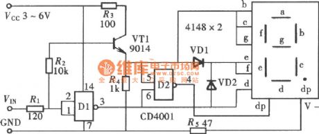
This figure shows a logic-pen that can tests and shows high level, low level and open state of the circuit.
(View)
View full Circuit Diagram | Comments | Reading(766)
Automotive Braking Air Under Pressure Protector One
Published:2011/7/29 4:15:00 Author:Felicity | Keyword: Automotive Braking, Air Under Pressure Protector
Work of the circuit
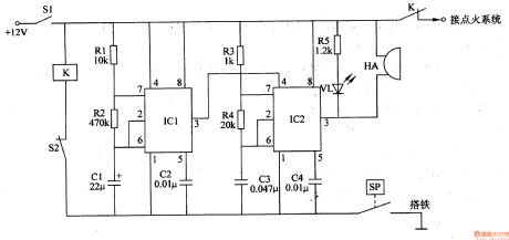
The circuit consists of control implementation circuit, low-frequency oscillator, audio oscillator, the pressure sensor SP, relay K and light and sound show circuit. (It is showed in picture 7-154.)
Control implementation circuit consists of relay K and clutch switch S2.
Low-frequency oscillator consists of time-base integrated circuit ICl, resistors Rl and R2 and capacitors Cl and C2.
Audio oscillator consists of time-base integrated circuit lC2, resistors R3 and R4 and capacitors C3 and C4.
Light and sound show circuit consists of resistor R5, light-emitting diodes VL and piezoelectric buzzer HA.
When the pressure of the reservoir is above the safe braking pressure, the contact inside pressure sensor SP releases and this protector doesn’t work.
When the pressure of the reservoir is under the safe braking pressure, the contact inside pressure sensor SP closes, and the low frequency and audio frequency oscillator are both at work (the low frequency oscillator modulate the audio frequency oscillator) to make VL shine and HA sends out alarm. At the same time , relay K closes , and the normally close contact releases to cut off the +12V power of the ignition system and the engine stops. (View)
View full Circuit Diagram | Comments | Reading(534)
Automotive Braking Air Under Pressure Protector Two
Published:2011/7/29 4:00:00 Author:Felicity | Keyword: Automotive Braking, Air Under Pressure Protector
Work of the circuit
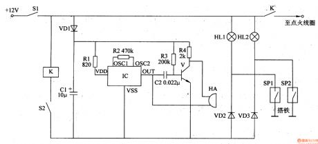
The circuit consists of air pressure sensor SPl, oil pressure sensor SP2, auto ignition switch Sl, clutch switch S2, buzzer HA, relay K, audio integrated circuit IC, transistor V, diode VDl-VD3, resistors Rl-R4, capacitors Cl and C2 and light HLl and HL2. (It is showed in picture 7-154.)
When the pressure of the braking air and the engine oil is normal, the contacts inside sensor SP1 and sensor SP2 releases. This circuit stands by.
When the pressure of the braking air and the engine oil is low, the contact inside sensor SP1 or sensor SP2 closes to make HL1 and VD2 or HL2 and VD3 on. And the relay K closes and the normally close contact cut off the +12V work power to extinguish the engine. At the same time IC works to make HA send out alarm. (View)
View full Circuit Diagram | Comments | Reading(577)
Automotive Braking Air Under Pressure Protector Three
Published:2011/7/29 3:58:00 Author:Felicity | Keyword: Automotive Braking, Air Under Pressure Protector
Work of the circuit
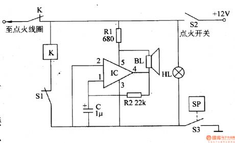
The circuit consists of speaker BL, voltage indicator HL, self-excited audio oscillator, the clutch switch S1, S2 and pressure sensing ignition switch S3. (It is showed in picture 7-155.)
Self-excited audio oscillator consists of power electronic switch IC IC (includes regulator, zoom, comparator, select 'pass to the ignition coil, plastic and power output and other circuits) and the resistors Rl and R2, capacitor C.
This automotive braking air under pressure protector consists of speaker BL, under pressure indicator HL, audio oscillator, clutch switch S1, ignition switch S2 and air pressure sensor switch S3.
When the braking pressure is normal, the contact inside S3 releases and this protector doesn’t work.
When the braking pressure is low, the contact inside S3 closes to make K closes too. And the normally close contact releases to cut off the power of the ignition system and the engine stops. At the same time, the under pressure indicator HL is on; the self-excited audio oscillator works; the speaker BL sends out alarm. (View)
View full Circuit Diagram | Comments | Reading(506)
Automotive Braking Air Under Pressure Protector Four
Published:2011/7/29 3:48:00 Author:Felicity | Keyword: Automotive Braking, Air Under Pressure Protector
Work of the circuit
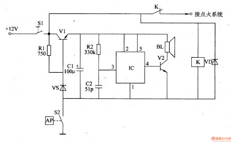
The circuit consists of pressure measurement and control circuit, voltage regulator filter circuit and voice alarm circuit. (It is showed in picture 7-156.)
Pressure measurement and control circuit consists of air pressure sensing switch S2, the ignition switch Sl, the relay K and diode VD.
Voltage regulator filter circuit consists of transistor Vl, resistors Rl, voltage regulator diode VS and filter capacitor Cl.
Voice alarm circuit consists of voice integrated circuit IC, resistor anal, capacitor C2, transistor V2 and the speaker BL.
When the braking pressure is normal, the contact inside S2 releases and this protector doesn’t work. The +12V power supplies for the ignition system through ignition switch S1 and the normally close contact of K.
When the braking pressure is below 25N/cm2, the contact of S2 closes to make K on. And the normally close contact releases to cut off the power of the ignition system and the engine stops. At the same time, after being regulated by V1, VS and smoothed by C1, the +12V voltage supplies IC for 3V direct work voltage. When IC is on, the vocal electrical signal output by pin 4 is amplified by V2 to drive BL to send out “Be care of the air pressure” voice. (View)
View full Circuit Diagram | Comments | Reading(526)
the circuit of whether rooster or hen discriminator(1)
Published:2011/7/15 21:46:00 Author:Ariel Wang | Keyword: rooster, hen , discriminator
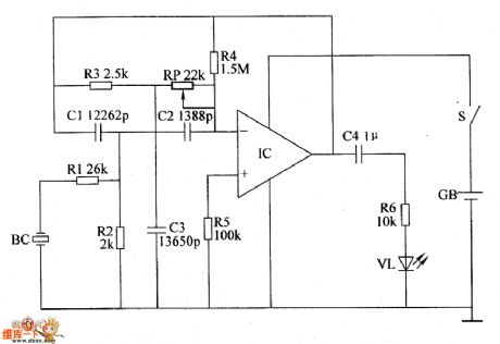
When the mains switch gets through,IC is conducted to work.BC converts the received chickling sound into the electric signal.It filtered the unwanted frequency below 5kHz by the active band-pass filter.It amplifies and outputs needed frequency signal.If the peeping chickling is hen.Then IC outputs voltage with signal.VL is lighted.If the peeping chickling is rooster.Then there is no signal output.VL is not lighted.You can adjust the resistence of RP.It can change the selective frequency of the active band-pass filter.So the identification of whether it's rooster or hen becomes more accurate.
(View)
View full Circuit Diagram | Comments | Reading(533)
the circuit of the automatic anti-frosting controller for crops(2)
Published:2011/7/15 21:46:00 Author:Ariel Wang | Keyword: automatic, anti-frosting , controller , crops
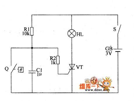
When the atmospheric temperature is higher than +1℃ ,the control contact of the electric contact mercury thermometer Q is connected(the mercury column goes over the control electrode,the mercury connects the control electrode and the contact electrode).The thyristor VT is stopped as the gate outputs low level.When the temperature goes down and the condition of frost is formed,the control contact of the electric contact mercury thermometer Q is disconnected(the mercury column goes beneath the control electrode,the control electrode and contact electrode are disconnected).The gate has the trigger high level.And VT is conducted.There is current passing through in the filament of HL.It lights the gunpowder.The smoking material is inflamed.
(View)
View full Circuit Diagram | Comments | Reading(495)
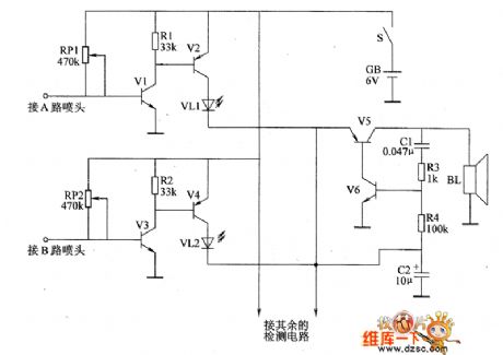
the alarm circuit of water break in the spray pipe for seeding-machine(2)
Published:2011/7/15 21:47:00 Author:Ariel Wang | Keyword: alarm , water break , spray pipe , seeding-machine
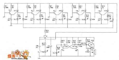
When the mains switch S gets through,the water break detected circuit and the sound and light alarm are conducted to work.When the spray pipe of any circuit is blocked,the SenseFET is conducted as the base electrode becomes high level.The transistor of the circuit is conducted.The LED of the circuit is lighted.It indicates how many the blocked spray pipes are.At the same time,V6 is conducted.The multivibrator and the controlled audio oscillatory circuit are conducted to work.B1 gives out alarm sound.For example,when the spray pipe of circuit A is blocked,there's no water spraying out from the sprayer in circuit A.V1,VT1 and V6 are conducted.VL1 is lighted.VL7 is lighted.BL gives out alarm sound.
(View)
View full Circuit Diagram | Comments | Reading(540)
the alarm circuit of water break in the spray pipe for seeding-machine(1)
Published:2011/7/15 21:50:00 Author:Ariel Wang | Keyword: alarm , water break , spray pipe , seeding-machine
When the mains switch S gets through,the water break detected cicWhen the mains switch S gets through,the water break detected circuit and the sound and light alarm are conducted to work.When the spray pipe of any circuit is not blocked,the base electrode of V1 and V3 are low level.V2,V4~V6 are not conducted.VL1 and VL3\2 are not lighted.BL doesn't give a sound. When the spray pipe of any circuit is blocked.The SenseFET of the circuit is conducted as the base electrode becomes high level.The LED of the circuit is lighted.It indicates how many the blocked spray pipes are.At the same time,the audio oscillatory circuit works.B1 gives out the alarm sound.
(View)
View full Circuit Diagram | Comments | Reading(598)
the fill light circuit of the chicken farm(1)
Published:2011/7/15 21:54:00 Author:Ariel Wang | Keyword: fill light, chicken farm
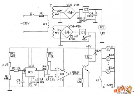
When in daylight,as the sunlight is strong,the resistance of RG is low.The pin-2 and pin-6 output high level.The pin-3 outputs low level.The pin-1 of IC4 outputs low level.V is stopped.K1 and K2 are not pulled in.The floodlights EL1~ELn are not lighted.In the rainy and cloudy day(in the day),the resistance of RC increases.The pin-2 and pin-6 of IC3 output low level.The pin-3 outputs high level.IC4 outputs high level as the voltage of non-inverting input end(pin-3) is higher than the voltage of inverting input end(pin-2).V is conducted.K1 is pulled in.The normally open contacts of K1 are connected.K2 is conducted to pull in.The floodlights EL1~ELn are conducted to be lighted.It provides light for the chicken house.
(View)
View full Circuit Diagram | Comments | Reading(532)
Positive dual periphery or driver circuit
Published:2011/7/27 2:10:00 Author:Fiona | Keyword: Positive dual periphery or driver circuit
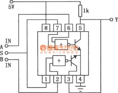
SN55453/75453B is a externaldrive with or logic and it’s input is compatible with TTL or DTL circuit. SN55453/75453B’s input current is 300mA,with high inputvoltageand high conversion speed. The typicalapplication circuitis shown as above.
(View)
View full Circuit Diagram | Comments | Reading(550)
TDA9302H pin function in color TV and data circuit
Published:2011/7/28 8:29:00 Author:Fiona | Keyword: pin function, color TV, data circuit
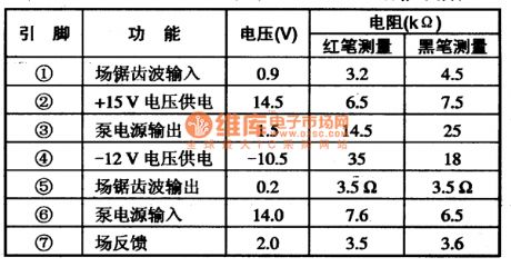
TDA9302H field scanning output integrated circuit
TDA9302H is a kind of new field scanning output intergrated circuit produced by Philips in the Netherlands.And it is widely used on Philips' new big-screen color TV .
1.Features
TDA9302H integrated circuit includes field excitation signal amplification circuit, field scanning output power amplifier circuit,field blanking pulse signal generating circuit, field scanning pump power supply circuit, and other auxiliary functions circuits.
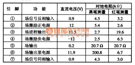
2. Pin function and data
TDA9302H integrated circuit uses 7-pin single in-line package, its pin function and data are listed in Table 71. Application data table is measured in Philips 29PT4423 big-screen TV.
(View)
View full Circuit Diagram | Comments | Reading(1139)
The Pin Function of TDA9302H on color image reveals and data circuit
Published:2011/7/27 1:58:00 Author:Fiona | Keyword: Pin Function, color image reveals, data circuit
TDA9302H integrated circuit is also widely used on various color monitors .Table 72 shows the measured data that when TDA9302H is applied in Tsinghua Tongfang 5E multi-frequencycolor monitor.
(View)
View full Circuit Diagram | Comments | Reading(594)
SN55452B/75452B positive dual periphery and Non-driver circuit
Published:2011/7/26 21:11:00 Author:Fiona | Keyword: positive dual periphery, non-driver circuit
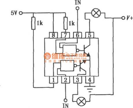
SN55451B/75451B is a externaldrive with NAND logic and it’s input is compatible with TTL or DTL circuit. SN55451B/75451B’s input current is 300mA,with high inputvoltageand high conversion speed. The typicalapplication circuitis shown as above.
(View)
View full Circuit Diagram | Comments | Reading(514)
SN55451B/75451B positive dual periphery and driver circuit
Published:2011/7/26 20:55:00 Author:Fiona | Keyword: positive dual periphery, driver circuit
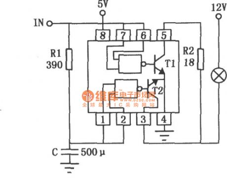
SN55451B/75451B is a externaldrive with and logic and it’s input is compatible with TTL or DTL circuit. SN55451B/75451B’s input current is 300mA.And it has high inputvoltageand high conversion speed. The typicalapplication circuitis shown as above.
(View)
View full Circuit Diagram | Comments | Reading(742)
SN55454B/75454B positive dual periphery or non-driver circuit
Published:2011/7/30 6:56:00 Author:Fiona | Keyword: positive dual periphery , non-driver circuit
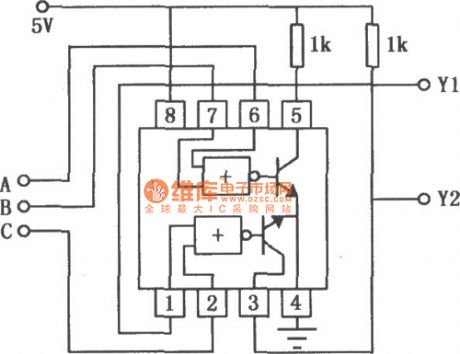
SN55454B/75454B is a externaldrive with NOR logic and it’s input is compatible with TTL or DTL circuit. SN55454B/75454B’s input current is 300mA,with high inputvoltageand high conversion speed. The circuit which is used as a multi-functional logic signal comparator to is shown as above.
(View)
View full Circuit Diagram | Comments | Reading(677)
SCR_CONTROLS_RITY_MOTOR
Published:2009/7/14 22:18:00 Author:Jessie
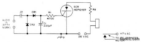
Single SCR can replace several transistor or tube stages in RTTY, VOX, COR, and other relay control circuits. Threshold triggering effect of SCR means triggering is automatically suppressed on low-level noise and similar interference. Used in RTTY autostart and motor delay sections of demodulator. Pickup time is 1 s and dropout time is 3 s, determined by values of R1 and C1 and by SCR, Circuit keys only on 2125-Hz mark tone. Diodes are 50-PlV silicon. Rd is appropriate dropping resistor for relay, if needed.-D, Weeden, SCR Relay Control for RTTY, VOX, and COR ,QSTT, July 1976, p 42. (View)
View full Circuit Diagram | Comments | Reading(1485)
HIGH_PRECISION_AUTO_TACHOMETER
Published:2009/7/16 3:15:00 Author:Jessie
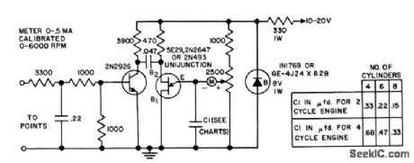
For auto ignition system having 12-v negative ground. Gives ultralinear readings on meter scale. Transistor Manual, Seventh Edition, General Electric Co., 1964, p 380. (View)
View full Circuit Diagram | Comments | Reading(624)
MAGNETIC_TAPE_CONTROL_OF_ENGINE
Published:2009/7/16 3:13:00 Author:Jessie

Auto engine parameters are recorded during road tests, and tapes are then used to program laboratory engine to simulate further tests. Synchronous switches Q2-Q3 and Q4-Q5, driven by line-frequency square-wave generator, operate as line-synchronous spdt switch, to place tape signal and lab-engine feedback signal on line alternately and synchronously with line voltage. Frequency-measuring circuit develops d-c voltage proportioned to input frequency. Output is used to drive two-phase motor that controls lab engine parameter.-V. C. Vanderbilt and C. L. Zimmer, Magnetic Tape Recorder Programs Engine Dynamometer Tests, Electronics, 33:51, p 74-77. (View)
View full Circuit Diagram | Comments | Reading(544)
_STARTER_CUTOFF
Published:2009/7/13 21:26:00 Author:May
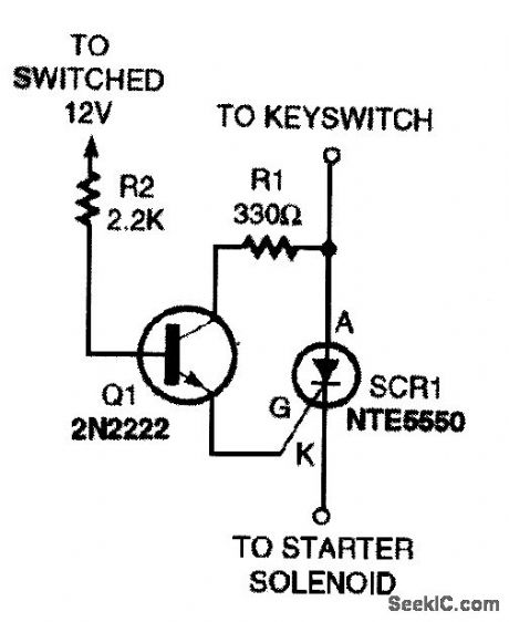
In this auto-starter cutoff circuit,two conditions are required to start the car∶The keys switcht must be turned to the starting position, and Q1 must be turned on When Q1 is switched to the ON state,current flOWS through the gate,allowing current to pass through the SCR,provided that the key switchis also turned to the starting position Transistor Q1 can be turned on by connecting R2 through a separate switch to a 12-V power Source or by usmg an existing switched Source Examples of existing Sources might be a brake light,turn signal, parking light,or anything that most people would not normally activate while starting a vehicle With regard to usmg a turn-signal indicator,it doesn’t matter that the power applied to Q1 is not constant Only a pulse IS required to latch the SCR on,provided that the key switch is in the starting position The SCR is a 25-A,50-V unit. (View)
View full Circuit Diagram | Comments | Reading(665)
| Pages:28/164 At 202122232425262728293031323334353637383940Under 20 |
Circuit Categories
power supply circuit
Amplifier Circuit
Basic Circuit
LED and Light Circuit
Sensor Circuit
Signal Processing
Electrical Equipment Circuit
Control Circuit
Remote Control Circuit
A/D-D/A Converter Circuit
Audio Circuit
Measuring and Test Circuit
Communication Circuit
Computer-Related Circuit
555 Circuit
Automotive Circuit
Repairing Circuit