
Automotive Circuit
Index 38
Differential Feeder Line Driver Circuit
Published:2011/7/18 2:57:00 Author:Sue | Keyword: Differential, Feeder Line, Driver
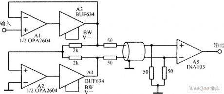
The picture shows the differential feeder line driver circuit. (View)
View full Circuit Diagram | Comments | Reading(504)
Precise Bridge Sensor Amplifier Circuit
Published:2011/7/18 2:51:00 Author:Sue | Keyword: Precise, Bridge, Sensor Amplifier
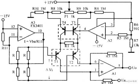
The picture shows the precise bridge sensor amplifier circuit. (View)
View full Circuit Diagram | Comments | Reading(551)
Instrumentation Amplifier Circuit with High Common-mode Range
Published:2011/7/18 2:49:00 Author:Sue | Keyword: Instrumentation Amplifier, High Common-mode

The picture shows the instrumentation amplifier circuit with high common-mode range. (View)
View full Circuit Diagram | Comments | Reading(419)
Duplicate Power Supply Reversed-Phase Input Alternating Current Amplifier Circuit
Published:2011/7/18 7:59:00 Author:Sue | Keyword: Duplicate Power Supply, Reversed-Phase, Input, Alternating Current, Amplifier

View full Circuit Diagram | Comments | Reading(457)
Toyota Land Cruiser 70 light off-road vehicle differential lockand door lock principle circuit diagram
Published:2011/5/8 12:41:00 Author:Rebekka | Keyword: Toyota Land Cruiser 70, light off-road vehicle, differential lockand door lock
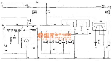
Toyota Land Cruiser 70 light off-road vehicle differential lockand door lock principle circuit diagram.
160 differential lock indicator light; 161 differential lock switch; 162 electronic differential lock control device; 163 differential lock motor; 164 door lock relay; 165 lock valve (pilot , the right crew, the crew left rear); 166 door lock switch (driver side); 167 door lock switch (no power windows and doors); 168 control switch (main switch electric windows and doors); 169 baggage door lock switch; 170 baggage door lock solenoid valve; 171 fuel heater; 69 combination instruments 7D terminal(four-wheel drive indicator light); 92 speed sensor.
(View)
View full Circuit Diagram | Comments | Reading(1623)
Infrared Remote Control Antitheft Coded Lock Circuit
Published:2011/7/16 6:40:00 Author:Sue | Keyword: Infrared, Remote Control, Antitheft, Coded Lock
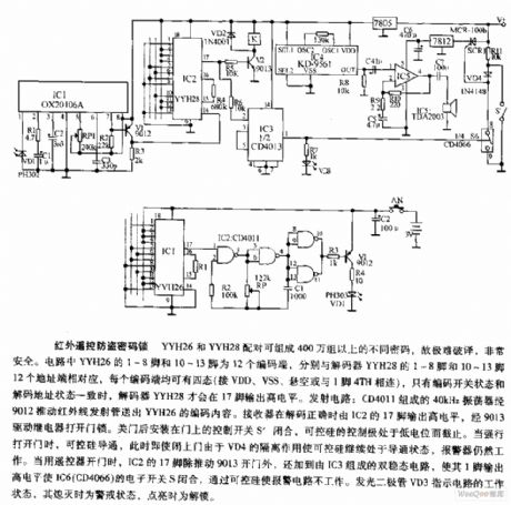
YYH26 and YYH28 can compose at least 4 million different groups of codes when these two are working in pairs. It is very different to decipher so it will be very safe. In the circuit, YYH26's pin 1-8 and pin 10-13 are 12 encoding terminals respectively which are corresponding to decoder YYH28's 12 address ports pin 1-8 and pin 10-13. Each encoding terminal can have 4 states(connect VDD,VSS,be suspend in air, or be connected to pin 1 4TH). Only when the encoding switch state is corresponding to the decoding address state, the decoder YYH28can output high level from pin 17. Emitting circuit: The 40kHz oscillator composed of CD4011 will output encoding content of YYH26 through 9012 push infrared ray transmitting tube. When encoding is correct, the receiver can output high level through IC2's pin 17 and unlock the lock by 9013 driven relay. When the door is closed, the control switch S' which is set on the door will be disconnected. Then the silicon control's control stage is disconnected because of low level. (View)
View full Circuit Diagram | Comments | Reading(466)
The public bus door shutting reminder
Published:2011/7/22 20:46:00 Author:qqtang | Keyword: public bus, door shutting reminder

The working principle of the circuitThe public bus door shutting reminder consists of the +12V resistors of R1 and R2, LED VL1-VL4, Hall sensors of 1 and 2, see as figure 7-115.
Hall sensor 1 and Hall sensor 2 are installed on the door frames of the bus, and in the corresponding places, there is a magnetic steel chip on either door. (View)
View full Circuit Diagram | Comments | Reading(440)
The steering lamp shutting reminder
Published:2011/7/22 20:33:00 Author:qqtang | Keyword: steering lamp, shutting reminder

Here is to introduce the steering lamp shutting reminder made of the 555 time based integrated circuit, which can emit the alarm signal when the driver forgets to shut off the steering lamp, so the driver will shut the lamp.The working principle of the circuit The steering lamp shutting reminder consists of the time-based integrated circuit IC, transistor V, diode VD, LED VL, resistor R1-R6, capacitor C1-C4 and buzzer HA, see as figure 7-118.
(View)
View full Circuit Diagram | Comments | Reading(444)
The motor headlight shutting reminder
Published:2011/7/22 20:58:00 Author:qqtang | Keyword: headlight, shutting reminder

The working principle of the circuitThe motor headlight shutting reminder consists of the light control switch circuit and audio alarm circuit, see as figure 7-119.
The light control switch circuit consists of the light sensitive resistor RG, resistor R3, capacitor C2 and transistor V.The audio alarm circuit consists of the time-based integrated circuit IC, resistors of R1 and R2, capacitor C1 and buzzer HA.GB is the battery of the motor, S1 is the car lock switch, S2 is the headlight switch, EL is the headlight. (View)
View full Circuit Diagram | Comments | Reading(784)
The motorcycle multi-functional reminder
Published:2011/7/22 9:56:00 Author:qqtang | Keyword: motorcycle, multi-functional reminder

The working principle of the circuitThe motorcycle multi-functional reminder consists of the diodes VD1-VD3, resistor R, regulated diode VS, filter capacitor C, music integrated circuit IC, transistor V and loudspeaker BL, see as figure 7-120.
S2 is the neutral switch, S3 is the steering lamp switch. HL1 is the neutral gear indicator, HL2 is the left turning lamp, HL3 is the right turning lamp. (View)
View full Circuit Diagram | Comments | Reading(487)
The car back-up alarm (1)
Published:2011/7/22 9:48:00 Author:qqtang | Keyword: back-up alarm

The working principle of the circuitThe car back-up alarm consists of 6 NOR gate integrated circuit IC(Dl-D6), transistor V, output transistor T and loudspeaker BL,etc, see as figure 7-121.
The internal NOR gates of D1-D6 of the IC, the external resistors of R3 and R7 and the capacitors of C3 and C2 compose the audio oscillator, which is used generate the basic frequency of the alarm sound. By changing the volumes of C2 and C3, the tone can be changed. (View)
View full Circuit Diagram | Comments | Reading(1545)
Audio Amplifier Circuit with Adjustable filter
Published:2011/7/18 3:08:00 Author:Sue | Keyword: Audio Amplifier, Adjustable, filter
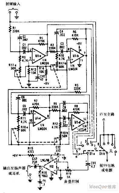
The audio amplifier uses two integrated circuit. It can tune between the range of 500Hz to 1500Hz, which can be used to drive loudspeaker or earphones. It can be used in clipped wave receiver or other receivers. (View)
View full Circuit Diagram | Comments | Reading(417)
The car burglarproof alarm (2)
Published:2011/7/23 20:46:00 Author:qqtang | Keyword: burglarproof alarm

Here is to introduce a car burglarproof alarm which utilizes the pulse signal generated when the engine oil meter and the sensor are working, the circuit is simple, and it can be used in both petrol engine and diesel engine.The working principle of the circuit The car burglarproof alarm circuit consists of the transistors V1 and V2, resistors R1-R3, capacitor C and burglar switch S1 and so on, see as figure 7-68.
When the burglarproof switch is at the gear of 2 , the former circuit is working normally, the burglarproof circuit is not working. (View)
View full Circuit Diagram | Comments | Reading(527)
Frequency Shift Keying(FSK) Signal Generator Circuit
Published:2011/7/21 0:44:00 Author:Sue | Keyword: FSK, Signal Generator

View full Circuit Diagram | Comments | Reading(553)
The car burglarproof alarm (3)
Published:2011/7/23 20:53:00 Author:qqtang | Keyword: burglarproof alarm
Here is to introduce a car burglarproof alarm which is installed in a hidden place, and it is used to confuse the thief, when the thief is stealing the motor, the motor seems to be ignited but doesn't move, finally, the motor can be ridden away, so the thief have to give up.The working principle of the circuit The car burglarproof alarm circuit consists of resistors R1-R5, capacitors C1-C5, diodes VD1-VD5, regulated diodes VS1-VS3, the transistor V, NAND integrated IC(D1 and D2) and relay K, see as figure 7-69.
(View)
View full Circuit Diagram | Comments | Reading(420)
Electric Fan Infrared Sensor(567) Circuit
Published:2011/7/21 0:42:00 Author:Sue | Keyword: Electric Fan, Infrared Sensor
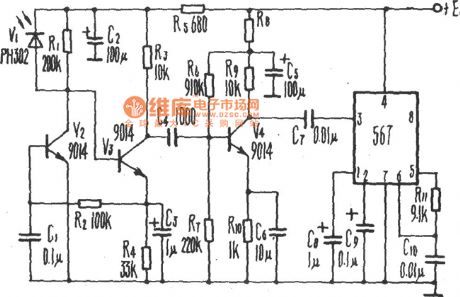
View full Circuit Diagram | Comments | Reading(914)
Domestic Appliance Infrared Remote Control Receiving Circuit
Published:2011/7/20 20:26:00 Author:Sue | Keyword: Domestic Appliance, Infrared Remote Control, Receiving
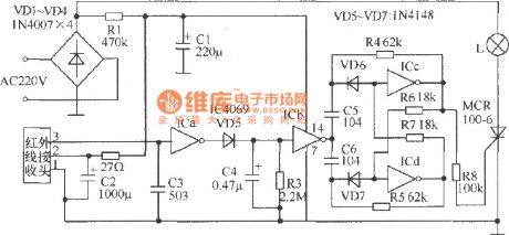
View full Circuit Diagram | Comments | Reading(428)
The motor burglarproof alarm (1)
Published:2011/7/23 20:18:00 Author:qqtang | Keyword: burglarproof alarm
Here is to introduce a motor burglarproof alarm which can make the motor normally ignite when it is at the neutral gear, and put out when it is put into gear. The thief would think the motor is malfunctioning and leaves the motor.The working principle of the circuit The motor alarm circuit consists of the transistors V1 and V2, transistor VT, diodes VD1-VD4, relay K, resistors R1-R3 and capacitor C, see as figure 7-70.
(View)
View full Circuit Diagram | Comments | Reading(405)
The motor burglarproof alarm (2)
Published:2011/7/23 20:24:00 Author:qqtang | Keyword: burglarproof alarm
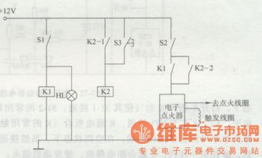
Here is to introduce the motor burglarproof alarm which adopts 2 relays as the burglarproof control part. When the thief ignite the engine with the skeleton key, just putting into gear will make the motor flameout, so the thief would think the motor is malfunctioning and leaves the motor.The working principle of the circuit The motor alarm circuit consists of the relays K1 and K2, control key S3, neutral switch S1, igniting switch S2 and so on, figure 7-71.
(View)
View full Circuit Diagram | Comments | Reading(411)
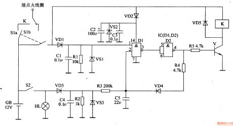
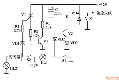
The motor burglarproof alarm (3)
Published:2011/7/23 20:30:00 Author:qqtang | Keyword: burglarproof alarm
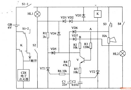
The working principle of the circuit
The motor alarm circuit consists of the diodes VD1-VD7, transistor V, thyristors VT1 and VT2, resistor R1-R6, capacitors C1 and C2, relay K, see as figure 7-72.
S1(S1-1, S1-2) is the motor lock switch, S2 is the neutral switch, S3 is the electric loudspeaker key, S4 is the brake switch. HL1 is the neutral gear indicator, HL2 is the brake lamp. GB is the motor battery. (View)
View full Circuit Diagram | Comments | Reading(436)
| Pages:38/164 At 202122232425262728293031323334353637383940Under 20 |
Circuit Categories
power supply circuit
Amplifier Circuit
Basic Circuit
LED and Light Circuit
Sensor Circuit
Signal Processing
Electrical Equipment Circuit
Control Circuit
Remote Control Circuit
A/D-D/A Converter Circuit
Audio Circuit
Measuring and Test Circuit
Communication Circuit
Computer-Related Circuit
555 Circuit
Automotive Circuit
Repairing Circuit