
Automotive Circuit
Index 39
The car burglarproof alarm (1)
Published:2011/7/23 20:38:00 Author:qqtang | Keyword: burglarproof alarm
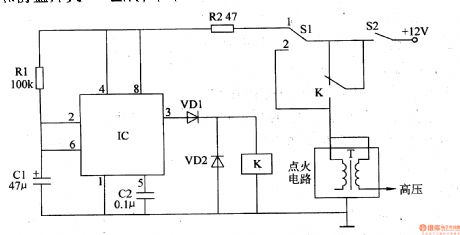
The working principle of the circuit The car burglarproof alarm circuit consists of the time-based integrated circuit IC, resistors R1 and R2, capacitors C1 and C2, diodes VD1 and VD2, relay K and burglarproof switch S1, see as figure 7-67.
Usually, the driver puts the hidden burglarproof switch at the point of 2 , the single steady time circuit consisting of IC, R1, R2, Cl and C2 does not work, the car can start and run normally. (View)
View full Circuit Diagram | Comments | Reading(459)
The storage battery voltage monitor (4)
Published:2011/7/23 21:38:00 Author:qqtang | Keyword: storage battery, voltage monitor

The working principle of the circuitThe battery voltage monitor circuit consists of resistors R1-R3, potentiometer RP, capacitor C, LED VL, regulated diode VS and time-based integrated circuit IC, see as figure 7-51.
The voltage of the battery GB is higher than 10.2V, the 3-pin of IC is outputing a low LEV, VL is not glowing; when the voltage of the battery GB is lower than 10.2V, the 3-pin of IC is outputting a high LEV, VL is glowing, the indicating batter voltage is too low. (View)
View full Circuit Diagram | Comments | Reading(450)
The battery charge/discharge monitor
Published:2011/7/23 21:29:00 Author:qqtang | Keyword: charge/discharge monitor
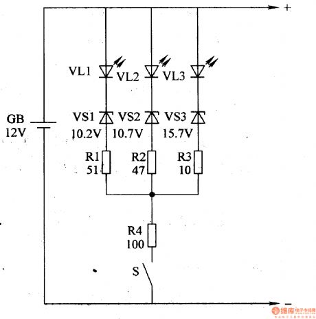
Here is to introduce a battery charge/discharge monitor which indicates the battery charge/discharge state with the 3R LED VL. The circuit is simple.The working principle of the circuitThe battery charge/discharge monitor circuits consist of the resistors R1-R4, LED VLl-VL3, regulator diodes VSl-VS3 and switch S, see as figure 7-52.
When charging, the voltage of VLl-VL3 on the battery terminal is rising to 16.2V, the indicators are all glowing, which means the battery is full and the charge current should be cut off or reduced. (View)
View full Circuit Diagram | Comments | Reading(1094)
The car brake lamp fault monitor (1)
Published:2011/7/23 20:59:00 Author:qqtang | Keyword: brake lamp, fault monitor
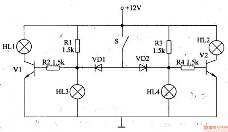
Whether the brake lamp is good directly affects the safety of the following car. Here is to introduce the car brake lamp fault monitor, which can find the broken lamp, reduce the traffic accidents and make sure the car is safe.The working principle of the circuit The car brake lamp fault monitor consists of the resistors V1 and V2, diodes VD1 and VD2, resistors R1-R4 and indicators HL1 and HL2, see as figure 7-53.
(View)
View full Circuit Diagram | Comments | Reading(530)
The car brake lamp fault monitor (3)
Published:2011/7/23 21:12:00 Author:qqtang | Keyword: brake lamp, fault monitor
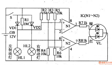
The working principle of the circuitThe car brake lamp fault monitor consists of the dimming LED VL, op-amp integrated circuit IC(N1 and N2) and relevant external elements, see as figure 7-55.
In the circuit, GB is the car storage battery, S is the brake switch, HL1 and HL2 are the left brake lamp and right brake lamp, respectively.
(View)
View full Circuit Diagram | Comments | Reading(494)
The car brake lamp fault monitor (4)
Published:2011/7/23 21:18:00 Author:qqtang | Keyword: brake lamp, fault monitor
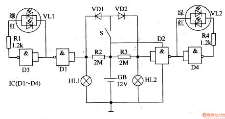
Here is to introduce a car brake lamp fault monitor circuit which is made of the CD4011 digital integrated circuit(4 NAND). The working principle of the circuitFigure 7-56 is the The car brake lamp fault monitor circuit
In the circuit, HL1 is the left brake lamp, HL2 is the right brake lamp, resistors R2 and R3 form 2 circuits with brake lamps HL1 and HL2. S is the brake switch, GB is the car battery. (View)
View full Circuit Diagram | Comments | Reading(512)
The car brake lamp fault monitor (5)
Published:2011/7/23 21:22:00 Author:qqtang | Keyword: brake lamp, fault monitor
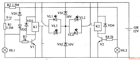
Here is to introduce a car brake lamp fault monitor circuit which is made of the separated element, it can detect the working state of the brake lamp and indicate the state with LED.The working principle of the circuitThe car brake lamp fault monitor circuits consists of the transistors V1 and V2, relays K1 and K2, diodes VD1-VD4, regulated diodes VS1 and VS2, LED VLl-VU and resistors R1-R4, see as figure 7-57.
(View)
View full Circuit Diagram | Comments | Reading(421)
The vehicle headlight monitor
Published:2011/7/23 4:08:00 Author:qqtang | Keyword: headlight monitor

The working principle of the circuit The vehicle headlight monitor circuit consists of the light sensitive transistor V1, transistors of V2 and V3, buzzer HA, LED VL and so on, see as figure 7-64.
At daytime, the phototransistor V1 is in a low LEV due to the light, so V2 is blocked due to the low LEV of its basic pole. If the driver forgets to shut off the headlight or mistakenly turn on the headlight, the basic pole of V3 will be in a low LEV, which makes V2 conducting, the buzzer HA is emitting the alarm sound, meanwhile, the LED VL is glowing. (View)
View full Circuit Diagram | Comments | Reading(592)
The car signal lamp monitor
Published:2011/7/23 3:54:00 Author:qqtang | Keyword: signal lamp, monitor
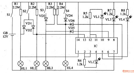
After the signal lamp is broken, if it is not replaced in time, the car is easy to cause accidents. Here is to introduce a car signal lamp monitor, which can emit red light alarm to remind the driver when the brake lamp or the turn lamp is malfunctioning.The working principle of the circuitThe car signal lamp monitor circuit consists of the diodes VD1-VD6, LED VL1-VL4, 6 NOR gate circuit IC and the external elements, see as figure 7-66.
(View)
View full Circuit Diagram | Comments | Reading(533)
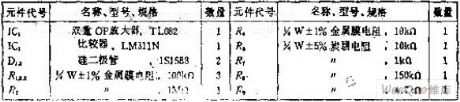
The zero differential coefficient peak time detection circuit
Published:2011/7/14 23:07:00 Author:Fiona | Keyword: zero differential coefficient, peak time detection circuit
Circuit Work
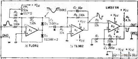
Circuit slightly is offset. Remove the noise of the input signal to make the circuit to avoid the error action.OP amplifier A1 is the ideal half-wave detector circuit.It outputs reverse signal, this signal is added to the differential circuit A2, and do the differential, and then seeks the zero-crossing time.Doing the zero-cross detection with comparator A3, the rising edge of the output pulse is the peak time. If the input waveformisthe same, there is nothing with its magnitude, only do zero-cross detection of the differential coefficient. Differential capacitor is 0.001UF, the input signal frequency range is about 100HZ ~ 10KHZ, if the input signal frequency is outside of this range, C1's capacity should be changed accordingly. (View)
View full Circuit Diagram | Comments | Reading(563)
The 2.5L(LBB) and 3.0L(LW9) engine circuit of Shanghai GM Buick-Regal(9)
Published:2011/7/20 2:19:00 Author:Borg | Keyword: engine circuit, Buick-Regal
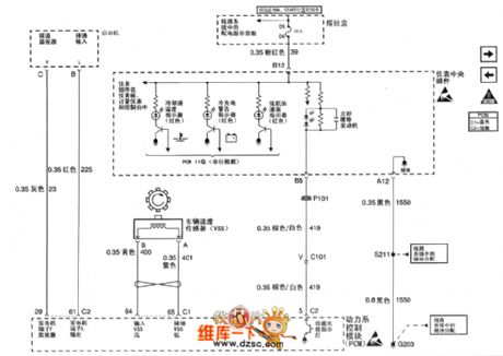
Figure 1. The 2.5L(LBB) and 3.0L(LW9) engine circuit of Shanghai GM Buick-Regal (9) (View)
View full Circuit Diagram | Comments | Reading(380)
The 2.5L engine transmission gear switch circuit of Shanghai GM Buick-MPV (GL8)
Published:2011/7/20 2:53:00 Author:Borg | Keyword: transmission, gear switch
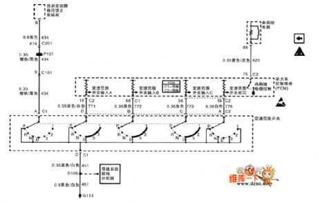
The 2.5L engine transmission gear switch circuit of Shanghai GM Buick-MPV (GL8)
(View)
View full Circuit Diagram | Comments | Reading(364)
The 2.5L(LBB) and 3.0L(LW9) engine circuit of Shanghai GM Buick-Regal (10)
Published:2011/7/20 2:16:00 Author:Borg | Keyword: engine circuit, Buick-Regal
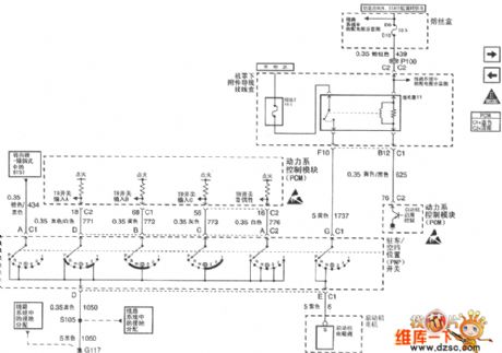
Figure 1. The 2.5L(LBB) and 3.0L(LW9) engine circuit of Shanghai GM Buick-Regal (10) (View)
View full Circuit Diagram | Comments | Reading(387)
The 2.5L(LBB) and 3.0L(LW9) engine circuit of Shanghai GM Buick-Regal (11)
Published:2011/7/20 2:16:00 Author:Borg | Keyword: engine circuit, Buick-Regal
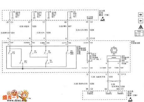
Figure 1. The 2.5L(LBB) and 3.0L(LW9) engine circuit of Shanghai GM Buick-Regal (11) (View)
View full Circuit Diagram | Comments | Reading(352)
The 3.0L engine A/C pressure sensor and admission temperature sensor circuit of Shanghai GM Buick-MPV (GL8)
Published:2011/7/20 2:52:00 Author:Borg | Keyword: A/C pressure sensor, admission temperature sensor
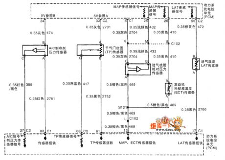
The 3.0L engine A/C pressure sensor, throttle position sensor, admission MAP sensor, auto speeder and admission temperature sensor circuit of Shanghai GM Buick-MPV (GL8)
(View)
View full Circuit Diagram | Comments | Reading(436)
The 3.0L engine emission recycle and power system control unit circuit of Shanghai GM Buick-MPV (GL8)
Published:2011/7/20 2:46:00 Author:Borg | Keyword: emission recycle, power system control unit
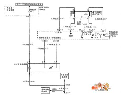
The 3.0L engine oxygen sensor, emission recycle and power system control unit circuit of Shanghai GM Buick-MPV (GL8)
(View)
View full Circuit Diagram | Comments | Reading(414)
The 3.0L engine air flow meter and vapor emission circuit of Shanghai GM Buick-MPV (GL8)
Published:2011/7/20 2:42:00 Author:Borg | Keyword: air flow meter, vapor emission, Buick-MPV
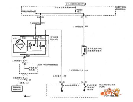
The 3.0L engine air flow meter and vapor emission circuit of Shanghai GM Buick-MPV (GL8)
(View)
View full Circuit Diagram | Comments | Reading(515)
The 3.0L engine oil level switch and oil pressure indicator circuit of Shanghai GM Buick-MPV (GL8)
Published:2011/7/20 2:39:00 Author:Borg | Keyword: oil level switch, oil pressure indicator
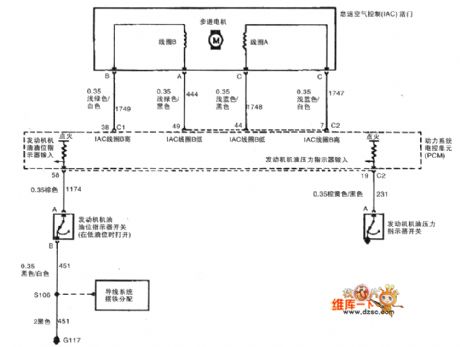
The 3.0L engine idle speed control, oil level switch and oil pressure indicator circuit of Shanghai GM Buick-MPV (GL8)
(View)
View full Circuit Diagram | Comments | Reading(483)
The 3.0L engine generator, dashboard and speed sensor circuit of Shanghai GM Buick-MPV (GL8)
Published:2011/7/20 2:36:00 Author:Borg | Keyword: engine generator, dashboard, speed sensor
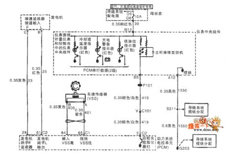
The 3.0L engine generator, dashboard and speed sensor circuit of Shanghai GM Buick-MPV (GL8)
(View)
View full Circuit Diagram | Comments | Reading(436)
The 2.5L engine idle speed valve and oil level sensor circuit of Shanghai GM Buick-MPV (GL8)
Published:2011/7/20 2:59:00 Author:Borg | Keyword: idle speed valve, oil level sensor
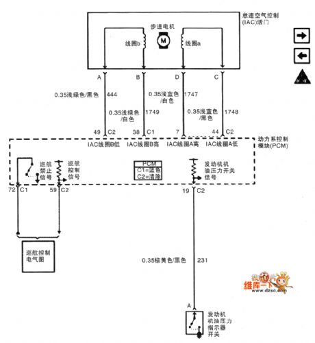
The 2.5L engine idle speed valve and oil level sensor circuit of Shanghai GM Buick-MPV (GL8)
(View)
View full Circuit Diagram | Comments | Reading(379)
| Pages:39/164 At 202122232425262728293031323334353637383940Under 20 |
Circuit Categories
power supply circuit
Amplifier Circuit
Basic Circuit
LED and Light Circuit
Sensor Circuit
Signal Processing
Electrical Equipment Circuit
Control Circuit
Remote Control Circuit
A/D-D/A Converter Circuit
Audio Circuit
Measuring and Test Circuit
Communication Circuit
Computer-Related Circuit
555 Circuit
Automotive Circuit
Repairing Circuit