Automotive Circuit
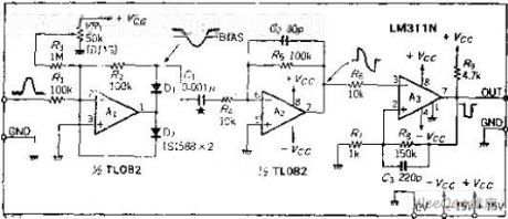
The zero differential coefficient peak time detection circuit
Published:2011/7/14 23:07:00 Author:Fiona | Keyword: zero differential coefficient, peak time detection circuit | From:SeekIC


Circuit Work
Circuit slightly is offset. Remove the noise of the input signal to make the circuit to avoid the error action.OP amplifier A1 is the ideal half-wave detector circuit.It outputs reverse signal, this signal is added to the differential circuit A2, and do the differential, and then seeks the zero-crossing time.Doing the zero-cross detection with comparator A3, the rising edge of the output pulse is the peak time. If the input waveformisthe same, there is nothing with its magnitude, only do zero-cross detection of the differential coefficient. Differential capacitor is 0.001UF, the input signal frequency range is about 100HZ ~ 10KHZ, if the input signal frequency is outside of this range, C1's capacity should be changed accordingly.
Reprinted Url Of This Article:
http://www.seekic.com/circuit_diagram/Automotive_Circuit/The_zero_differential_coefficient_peak_time_detection_circuit.html
Print this Page | Comments | Reading(3)

Article Categories
power supply circuit
Amplifier Circuit
Basic Circuit
LED and Light Circuit
Sensor Circuit
Signal Processing
Electrical Equipment Circuit
Control Circuit
Remote Control Circuit
A/D-D/A Converter Circuit
Audio Circuit
Measuring and Test Circuit
Communication Circuit
Computer-Related Circuit
555 Circuit
Automotive Circuit
Repairing Circuit
Code: