Automotive Circuit
SMART_TURN_SIGNAL_FOR_AUTOS_AND_MOTORCYCLES
Published:2009/6/19 2:24:00 Author:May | From:SeekIC

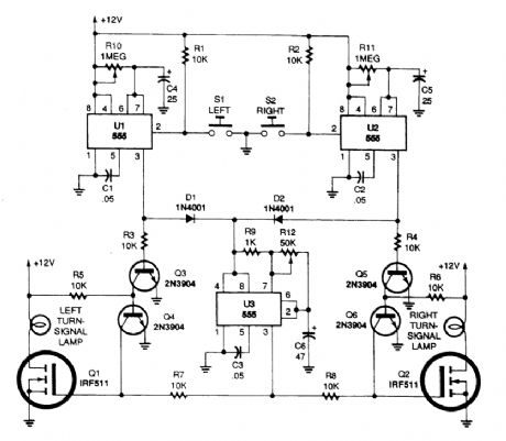
Momentarily pressing S1 starts the left on-time timer and produces a positive output at pin 3 of U1. Power for the on/off signal timer, U3, is supplied through D1.Also, a positive bias is supplied from U1's output to the base of Q3, turning it on and turning Q4 off. Unclamped Q1 turns the left turn-signal lamp on and off at that same low-frequency rate. Because U2 is not activated, its output at pin 3 is low, keeping Q5 off. With Q5 turned off, Q6 is on, clamping the gate of Q2 to ground and keeping it from responding and supplying an output for the right turn-signal lamp. The left turn signal continues to operate until the UI timer circuit times out; the right turn signal operates in a similar manner, with U2 setting its operating time.Potentiometer R10 sets the running time for the left turn signal and R11 sets that for the right turn signal.
Reprinted Url Of This Article:
http://www.seekic.com/circuit_diagram/Automotive_Circuit/SMART_TURN_SIGNAL_FOR_AUTOS_AND_MOTORCYCLES.html
Print this Page | Comments | Reading(3)

Article Categories
power supply circuit
Amplifier Circuit
Basic Circuit
LED and Light Circuit
Sensor Circuit
Signal Processing
Electrical Equipment Circuit
Control Circuit
Remote Control Circuit
A/D-D/A Converter Circuit
Audio Circuit
Measuring and Test Circuit
Communication Circuit
Computer-Related Circuit
555 Circuit
Automotive Circuit
Repairing Circuit
Code: